
 Call Us Now !
Tel : +86 755 27374946
Call Us Now !
Tel : +86 755 27374946
 Order Online Now !
Email : info@bichengpcb.com
Order Online Now !
Email : info@bichengpcb.com
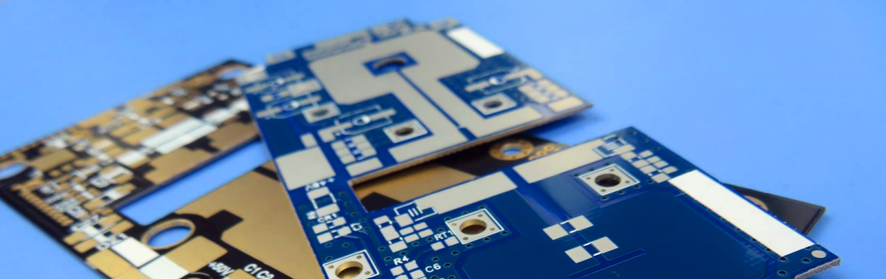
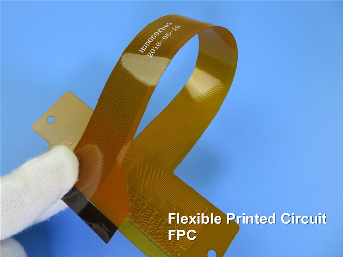
Flexible Printed Circuit Board
1, Purpose of Flexible Circuits
◆to provide interconnections between printed circuit boards and other components.
◆to serve as three-dimensional substrates for the mounting of SMT components, e.g. in mobile phone, digital camera and video cameras etc.
◆to establish interconnections capable of withstanding dynamic flexing.
◆to form part of flex-rigid circuit boards.
2, Basic Types of Flexible Circuit
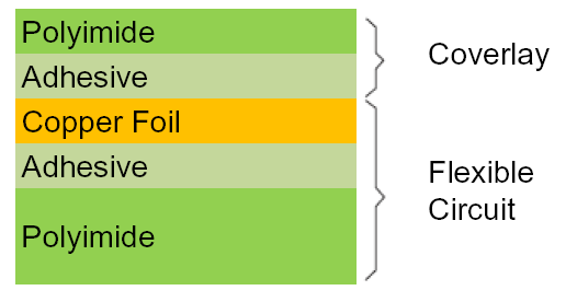
◆ Single-Sided Flexible Circuits
This is the simplest type, and consists of a thin and flexible base material to which a copper foil is laminated by means of an adhesive. The finished circuit is frequently provided with a coverlay bonded to the copper side by means of an adhesive. Holes for components or connector pins are drilled or punched in the flexible circuit to provide non-plated-through holes. Holes in the coverlay are drilled or punched before bonding the coverlay to the flexible circuit.
◆ Double-Sided Flexible Circuits
As the name suggests, the circuit consists of a thin and flexible base material with copper foil laminated to each side. The outer sides of the finished circuits are frequently provided with coverlays bonded to the outer sides (copper). Plated-through holes in double-sided flexible circuits are usually drilled, instead of punched. Usually the flexible circuits are provided with a coverlays on both sides
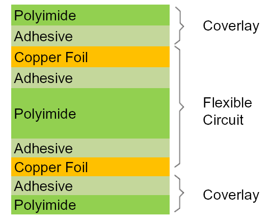
◆ Multilayer Flexible Circuits
A multilayer flexible circuit consists of a number of thin and flexible base laminates and copper foils laminated together by means of adhesive, in very much the same way as rigid multilayer boards. Also it is common practice to bond coverlays to the outer sides (copper). Plated-through holes can be provided in virtually the same way as in double-sided flexible circuits.

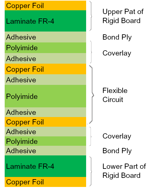
◆ Flex-Rigid Circuits
A flex-rigid circuit is a combination of rigid boards and flexible circuits, the latter creating flexible inter-connects between the rigid boards to which they are laminated by means of bond plies. The flexible circuit is manufactured separately and bonded to the rigid boards, either symmetrically, i.e., in the middle of the rigid boards, or asymmetrically, i.e., to the outer side of the rigid boards to be interconnected. Plated-through holes are provided in the rigid sections of the flex-rigid circuits to establish electrical connection between the interconnect (the flexible circuit section) and the electronic circuits of the rigid boards. The processes are similar to those used when manufacturing rigid multilayer boards.
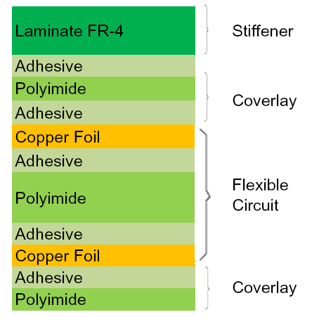
◆ Flexible Circuits with Rigid Areas
In some cases, the flexible circuit must support a number of relatively heavy components or even a connector part. Therefore it is necessary to reinforce such an area. This is accomplished by bonding a stiffener to that area. The stiffener can be an extra layer of not too thin polyimide, or it can be a glass/epoxy laminate. The stiffener is provided with holes larger than the pads of the plated-through holes.
3. Components of a flexible circuit
A flexible circuit consists of copper foil, dielectric substrate and coverlay, and adhesive.
Copper foil is available in two different types of copper: ED Copper and RA copper.
ED copper is an electro-deposited (ED) copper foil produced in the same way as the copper foil used for rigid printed circuit boards. This also means that the copper is “treated”, i.e., it has a slightly rough surface on one side, which ensures a better adhesion when the copper foil is bonded to the base material.
RA copper is a rolled and annealed copper foil produced from electrolytically deposited cathode copper, which is melted and cast into ingots. The ingots are first hot-rolled to a certain size and milled on all surfaces. The copper is then cold-rolled and annealed, until the desired thickness is obtained.
Copper foil is available in thickness of 12, 18, 35 and 70 µm.
The most common available for dielectric substrate and coverlay is polyimide films. This material can also be used as coverlay. Polyimide is best suited for flexible circuits because of its characteristics as stated below:
◆ High temperature resistance allows soldering operations without damaging the flexible circuits
◆ Very good electrical properties
◆ Good chemical resistance
Polyimide is available in thicknesses of 12.5, 20, 25 and 50 µm.
Base laminates for rigid printed circuit boards are copper foils laminated together with the base materials, the adhesive coming from the prepreg material during lamination. Contrary to this is the flexible circuit where the lamination of the copper foil to the film material is achieved by means of an adhesive system. It is necessary to distinguish between two main systems of adhesive, namely thermoplastic and thermoset adhesives. The choice is dictated partly by the processing, and partly by the application of the finished flexible circuit.
4. Semi-manufactures
A selection of semimanufactures is available today, so the manufacturers of flexible circuits do not have to start with the base materials: copper foil, dielectric substrates and adhesives. The adhesive is always in a B-stage, i.e. semi-cured and non-tacky, so that handling of the material, e.g., drilling and lay-up, is possible.
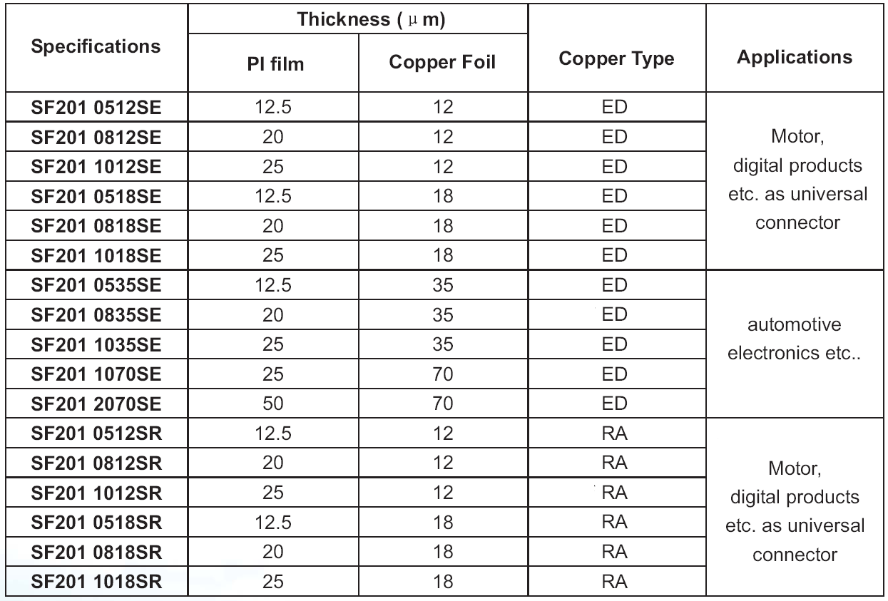
Copper Clad Polyimide Films
Following is specifications of single side adhesiveless flexible copper clad laminate
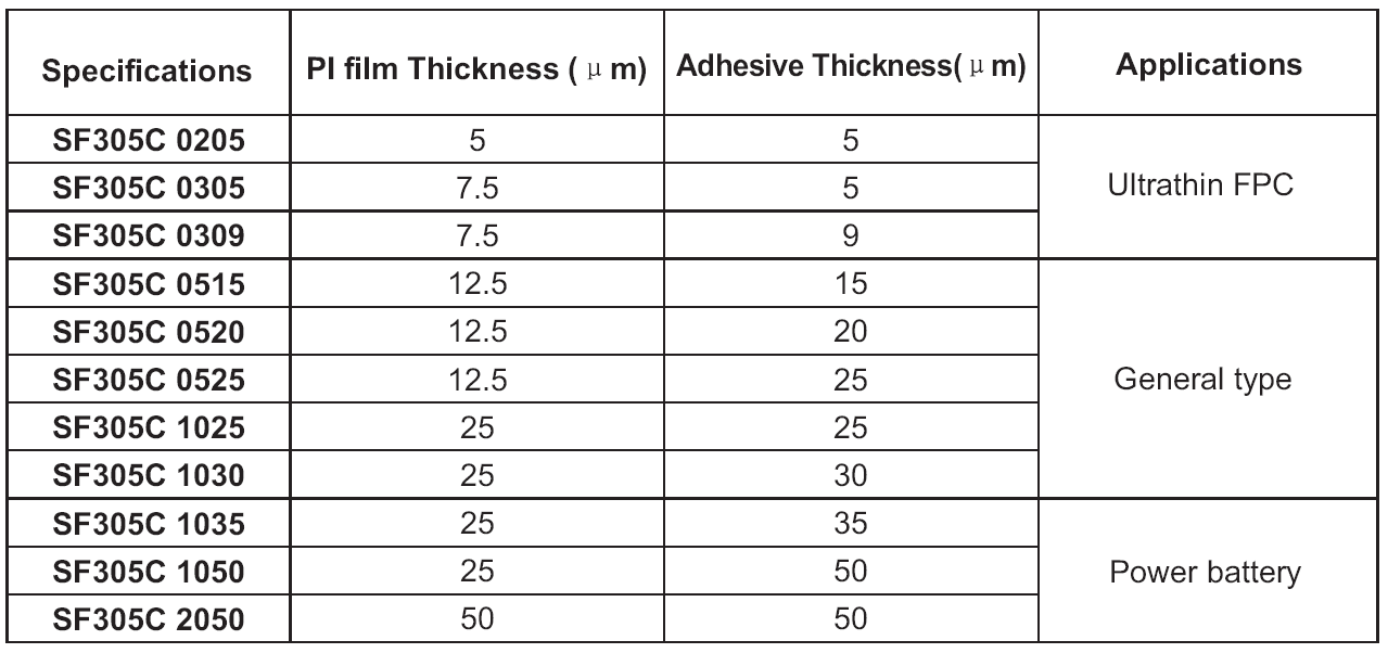
Coverlay Materials
Semimanufactures for coverlay in the form of a polyimide film with a layer of adhesive are also available. There are a variety of thicknesses of films and adhesives as shown below.
Bond Plies
In some cases, the build-up requires a polyimide film with an adhesive layer on both sides.

This is also possible to buy semimanufactures. Bond plies are available in a variety of different thicknesses as shown below.

5. Manufacturing processes
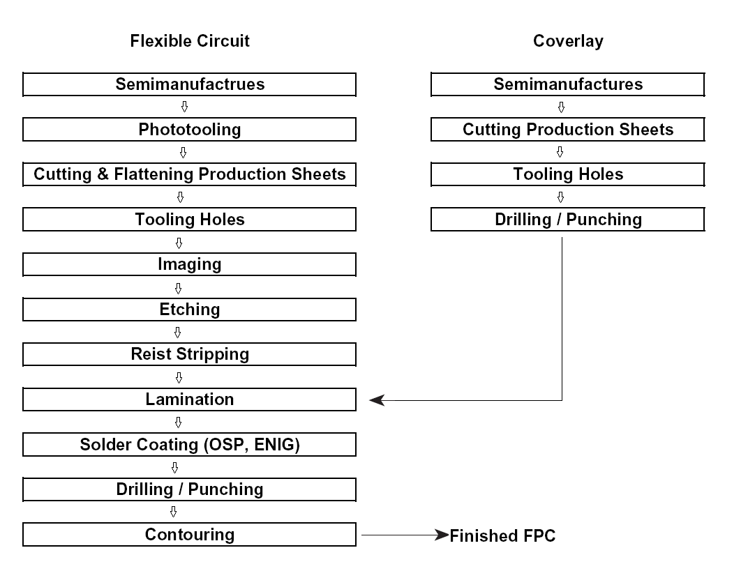
5.1 Single-Sided Flexible Circuits
The most straightforward flexible circuit is single-sided and non-plated. However, during manufacture, it is necessary to take precautions to avoid any deformation or tearing of the thin and highly flexible material. A flow diagram is shown below.
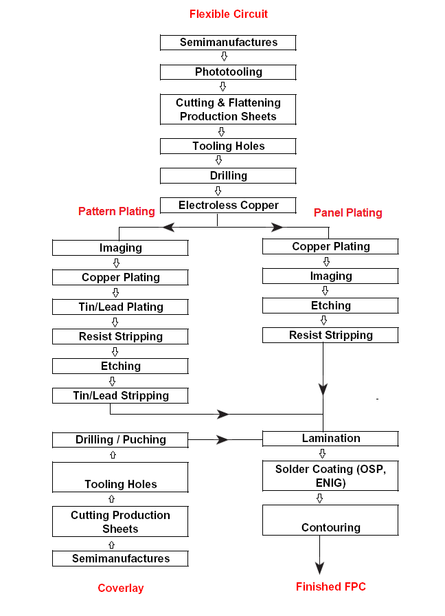
5.2 Double-Sided Plated-Through Flexible Circuits
Although manufacture of double-sided, plated-through flexible circuits, generally, resembles that of single-sided non-plated-through boards, some of the manufacturing processes are new and/or appear in another sequence. A flow diagram of the processes is shown below.
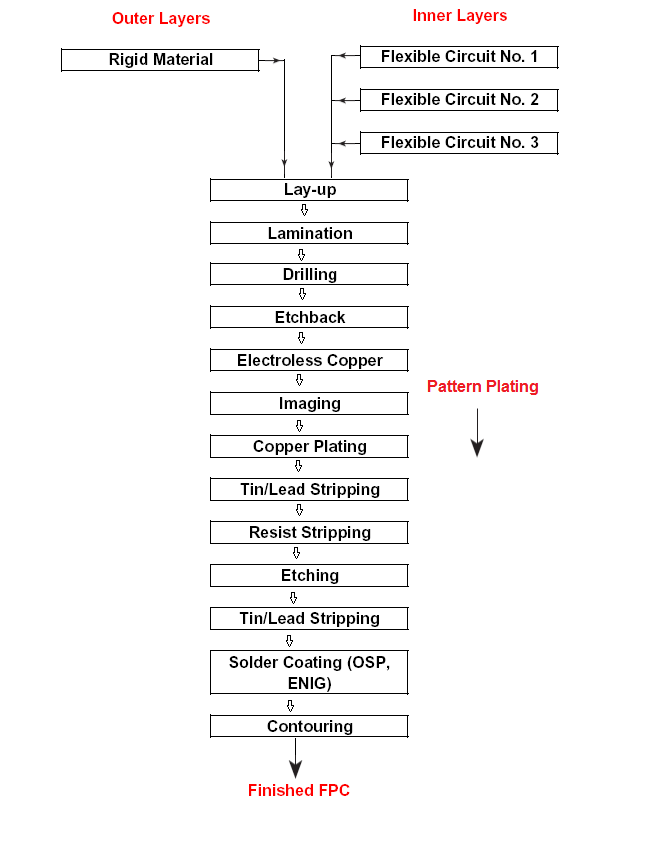
5.3 Multilayer Flexible Circuits and Rigid-Flex Circuits
For a number of reasons, it is not recommended to combine too many flexible circuits into a multilayer flexible circuit.
Materials and Thicknesses
It is common practice to use the materials listed below.
Dielectric Substrates
50 µm (2 mil) polyimide because of its higher stability and easier handling compared with 25 µm (1 mil) polyimide.
Copper Foil
35 µm (1 oz.) copper foil, provided this thickness is compatible with the current carrying requirements of the finished circuit.
Coverlay
25 µm (1 mil) polyimide for a 35 µm (1.4 mil) thick copper foil, since it ensures a better encapsulation of the conductors than a 50 µm (2 mil) polyimide. 25 µm (1 mil) acrylic adhesive for achieving a good encapsulation and a low-flow lamination. Too much acrylic adhesive leads to reliability problems, e.g. barrel cracks, foil cracks, and a too deep etchback.
Outer Layers
Outer layers should not be provided with any circuitry (conductors) on the bonding side because of the risk of air entrapment at the interface.
For multilayer flexible circuits 50 µm (2 mil), polyimide is used for outer layers, whereas for flex-rigid circuits rigid materials are used, frequently glass epoxy FR-4 or polyimide reinforced with glass fabric.
In some cases, polyimide composites (copper-clad polyimide films with adhesive on the bonding side) are used in thick flex-rigid circuits, because the overall thickness makes the circuit sufficiently rigid for carrying the components.
Bonding Materials
When using coverlayed flexible circuits as inner layers, the circuits and the rigid parts are bonded together by means of sheet adhesives.
A simplified flow process diagram is shown below.
Previous :
How to specify a PCB?Next :
What is high Tg PCB? 6-11C Shidai Jingyuan, Fuyong, Baoan, Shenzhen, Guangdong, China 518103


For inquiries about our products or pricelist, please leave to us and we will be in touch within 24 hours.
© Copyright: 2026 Shenzhen Bicheng Electronics Technology Co., Ltd.. All Rights Reserved.

IPv6 network supported


