How to Distinguish the Step (Stack-up) of HDI
PCB?
Tag#Stacked via Staggered via HDI | PCB 1+N+1
HDI PCB | 2+N+2 HDI PCB
HDI stands for high density interconnection. It
contains non-mechanical drilling, the ring of microvias and blind via below 6 mil, internal and external layers of
track width, track gap below 4 mil, pad diameter is not more than 0.35 mm. We
call this kind of multi-layer PCB production method as HDI circuit boards. HDI
PCB has a higher wiring density per unit area than conventional PCB. They have
finer tracks and spaces, smaller vias and capture pads and higher connection
pad density etc.
I.Holes
and vias
Plated through hole: There is only one kind of
hole, from the first layer to the last layer. Whether external or internal
lines, holes are pierced. It's called a through-hole board.
The through-hole board has nothing to do with
the number of layers. Usually, the two layers used by everyone are through-hole
boards, while many switches and military circuit boards up 20 layers, they're
still through holes. The circuit board is drilled through with a drill bit, and
then copper in the hole to form a path. Note here that the through hole
diameter is usually 0.2 mm、0.25mm
and 0.3 mm, but generally 0.2 mm is much more expensive than 0.3mm. Because the
bit is too thin and easy to break, the drill works slower. The cost of time and
bit is reflected in the rising price of the circuit board.
Blind via : the abbreviation of blind via hole,
realize the connection between inner layer and outer layer.
Buried via: the abbreviation of buried via
hole, realize the connection between inner layer and inner layer.
Most of the blind vias / buried vias are small
holes with a diameter of 0.05 mm~0.15 mm. The blind vias and buried vias are
made by laser drill, plasma etching and photoinduced drill. Usually laser drill
is the most commonly used. Laser formation is usually divided into CO2 and YAG
ultraviolet laser machine (UV).
Expansion: CO2 laser is
generally 10.6µm
light wave infrared light, using CO2 gas medium to produce laser, so called gas
laser. In the scope of use, it's generally used in non-metallic marking,
welding and cutting, the high power can also be used in metal cutting. Early
CO2 lasers had higher power, so gas lasers are popularly used in processing.
YAG solid-state laser generally refers to 1064
nm infrared wavelength laser, using solid-state excitation medium, commonly
known as solid-state laser, solid-state laser wavelength is shorter, processing
efficiency is higher, with the development of technology, the power is also
getting higher and higher. CO2 lasers have been replaced in many applications.
II. Types of Steps (Stack-ups)
In China, we usually use "Steps" to
tell the different difficulties of HDI PCBs, One-Step (1+N+1), Two-Step (2+N+2),
Three-Step (3+N+3) etc. The way to distinguish the one, two, three steps is to
look at the number of using laser times. That how many times of PCB core
pressed uses how many times of laser drilled, this is the "Steps".
This is the only difference.
1, Press once and drilling ==> out-layer
press copper foil ==> and laser drilling, this is one step (1+N+1), as shown
below

2. Press once and drilling ==> outlayer
press copper foil ==> laser drilling ==> outer layer press copper foil
==> laser drilling again. Here is the two steps (i+N+i, i≧2). It mainly is
to see how many times of laser drilling, it is the number of steps.
The Two-Step is divided into two types: stacked
holes and staggered holes.
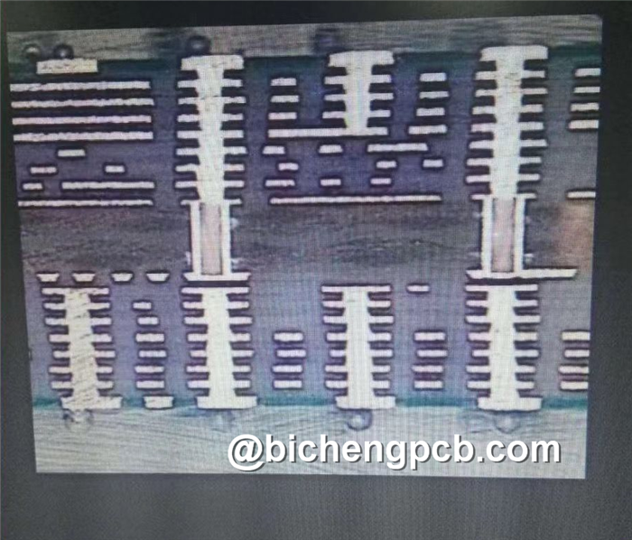
The following picture is an eight-layer stacked
holes of Two-Step HDI ,3-6 layers are first pressed, then the outside 2nd layer
and 7th layer are pressed up, processing laser drill first time. after then,
press 1st and 8th layers up and laser drill again. It's two times of laser
drill. Since these vias are superimposed (stacked), the process will be a
little more difficult and the cost is a little higher.

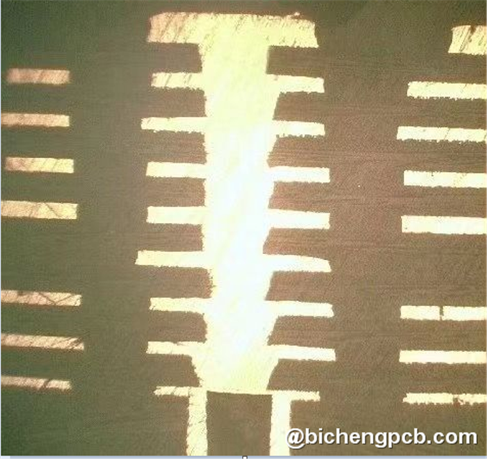
The following picture is an eight-layer
staggered holes of Two-Step HDI. . This processing method, like the upper
eight-layer Two-Step stacked hole, also requires two times of laser drill. But
laser drill are not stacked together, processing is much less difficult.
The Three-Step, Four-Step are by analogy.
In August of 2020, Bicheng announced that Eight-Step
HDI PCB trial-production was successfully launched in our factory for the
market.


 Call Us Now !
Tel : +86 755 27374946
 Order Online Now !
Email : info@bichengpcb.com


