
 Call Us Now !
Tel : +86 755 27374946
 Order Online Now !
Email : info@bichengpcb.com
Can One Rogers RO4003C 1100x350mm Double-Sided HF PCB Replace Spliced Antenna Sub-Boards?
Yes. When a single radiating aperture, feed network or sensor array is longer than a standard board and must stay electrically continuous, one Rogers RO4003C 1100x350mm double-sided HF PCB removes the connectors and splices that quietly degrade large antenna designs. It is not the cheapest option and it is overkill for many circuits, but for long, controlled-impedance arrays it trades a modest increase in material and handling cost for fewer joints, lower loss and more repeatable phase response. This guide covers when that trade is justified, what the data supports, and what to verify before ordering.
As gain rises and beam-width tightens, the radiating aperture grows. A high-gain sector antenna, a long slot array or a series-fed patch column can easily stretch past half a metre. The usual response is to tile the aperture: split the array across several smaller boards and connect them with coaxial jumpers, edge-launch connectors or soldered butt joints. Every connection works, but every connection is a discontinuity. At microwave frequencies, a millimetre of mismatch or a single connector is a meaningful fraction of a wavelength. It adds insertion loss and return loss, can generate passive intermodulation, and forces the designer to budget phase and amplitude error between sections. It also adds components, assembly labour and extra field-failure points.
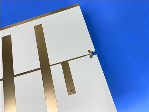
A 1100 × 350 mm Rogers RO4003C double-sided HF PCB is produced as one continuous panel rather than a set of butted sub-boards. The 1100 mm dimension is not arbitrary: Rogers lists RO4003C panels up to 48 × 36 in (1219 × 915 mm), so a 1.1 m board fits inside a genuine single sheet with no edge-joined dielectric. The whole array then shares one substrate lot, one copper treatment and one uninterrupted reference plane.
|
Design factor |
Tiled sub-boards |
Single 1100 × 350 mm RO4003C panel |
|
Electrical continuity |
Interrupted by connectors or butt joints |
Continuous dielectric and ground plane |
|
Phase / amplitude match |
Error budgeted at every transition |
One material lot, end to end |
|
Insertion loss |
Added at each splice |
No splice across the aperture |
|
Parts and assembly |
Jumpers, connectors, alignment labour |
One bare panel, fewer line items |
|
Handling and shipping |
Small boards, tolerant of handling |
Panel over 1 m needs support and care |
|
Cost of entry |
Lowest board cost |
Higher material and handling cost |
Table 1. Design trade-offs between a tiled aperture and a single oversized RO4003C panel.
The benefits are real but bounded. A panel longer than a metre is more awkward to handle and needs support during assembly and shipping. It is the right call when electrical continuity matters more than those logistics.
The material does the electrical work. Above roughly 500 MHz, ordinary epoxy/glass (FR-4) shows higher, less controlled loss and a dielectric constant that varies more with frequency and temperature. RO4003C is a woven-glass-reinforced hydrocarbon/ceramic laminate — not PTFE — specified with a process dielectric constant of 3.38 ± 0.05 at 10 GHz and a design Dk of 3.55 across 8–40 GHz. Its dissipation factor is 0.0027 at 10 GHz and 0.0021 at 2.5 GHz, and the thermal coefficient of its dielectric constant is only +40 ppm/°C from −50 to 150 °C. In practice, an impedance target or resonator dimension set at room temperature stays close over the operating temperature range and across a long, multi-element array.
The mechanical figures matter just as much at this size. Coefficients of thermal expansion are 11, 14 and 46 ppm/°C in the X, Y and Z axes; the in-plane values are close to copper, underpinning reported dimensional stability below 0.3 mm/m and reliable plated through holes. A glass transition temperature above 280 °C and a decomposition temperature of 425 °C suit lead-free assembly, and moisture absorption of 0.06% is helpful for outdoor antennas. Two caveats matter: RO4003C is non-brominated and is not UL 94 V-0 rated (specify RO4350B or RO4835 where a flame rating is mandatory), and it costs more than FR-4. Unlike PTFE microwave laminates, however, it processes on standard FR-4 equipment with no sodium-etch or special hole preparation, which keeps conversion cost and lead time predictable.
On an RF radiating surface, the solder mask and silkscreen found on most boards are deliberately left off. Solder mask is itself a dielectric: placed over a microstrip patch or feed it shifts the effective dielectric constant, adds frequency-dependent loss, and introduces coating-tolerance and moisture effects that are difficult to model. Leaving the 1 oz outer copper exposed means the fields see only the Rogers 4003C core and air, exactly as simulated.
Exposed copper still needs protection, which is the role of electroless nickel/immersion gold (ENIG). On this board the immersion gold is 2 μin over a nickel barrier, providing a flat, planar surface for pads and contacts, good oxidation resistance and consistent solderability without the thickness variation of organic finishes. The dielectric core is 0.813 mm (32 mil), a standard RO4003C gauge supplied to ±0.0020 in.
1) Confirm panel and capability fit. Verify the fabricator can genuinely process the 1100 mm axis from a single sheet and handle a panel over one metre long, rather than edge-joining smaller stock.
2) Use the right Dk for each job. Use the design Dk (3.55) for impedance and resonator calculations at 8–40 GHz, and treat the tightly controlled process Dk (3.38 ± 0.05) as the incoming-material specification.
3) Model the bare surface and the finish. Design for no solder mask over radiating elements and specify the ENIG gold thickness explicitly; if wire bonding or higher contact wear is expected, confirm the gold thickness suits that use.
4) Qualify the environment and the test. For space use, note the NASA SP-R-0022A outgassing data: RO4003C measured 0.06% total mass loss and 0.00% collected volatiles, well inside the 1.0% / 0.1% low-outgassing limits. Require 100% electrical test on a panel this size, since an untested section is expensive to discover after assembly.
Q: Is RO4003C a PTFE material?
A: No. It is a ceramic-filled hydrocarbon laminate reinforced with woven glass, delivering PTFE-class high-frequency performance while processing like FR-4.
Q: Can a 1100 mm board really be one continuous panel?
A: Yes, where the fabricator can use Rogers' 48 × 36 in (1219 × 915 mm) sheet and has the handling capability; it is not a butt-joined set of sub-boards.
Q: Is omitting solder mask on an antenna normal?
A: It is common and intentional. Bare radiating surfaces keep the electromagnetic environment equal to the core and air used in simulation; ENIG protects the copper.
Q: Is RO4003C flame-rated?
A: It is not UL 94 V-0. Choose RO4350B or RO4835 when a V-0 flame rating is a design requirement.
A Rogers RO4003C 1100x350mm double-sided HF PCB is a targeted answer to a specific problem: an antenna or feed array that is too long to tolerate splices. Its low, stable dielectric loss, copper-matched expansion, bare RF surfaces and ENIG finish, combined with genuinely continuous construction, address the real failure modes of large arrays — splice loss, phase mismatch, corrosion and latent opens. For simple, low-frequency or cost-driven boards, FR-4 or a tiled assembly remains the sensible choice; for a large, performance-sensitive aperture that must behave as one circuit, the single oversized panel earns its cost.
Categories
New Blog
Tags
 6-11C Shidai Jingyuan, Fuyong, Baoan, Shenzhen, Guangdong, China 518103


For inquiries about our products or pricelist, please leave to us and we will be in touch within 24 hours.
© Copyright: 2026 Shenzhen Bicheng Electronics Technology Co., Ltd.. All Rights Reserved.

IPv6 network supported


