
 Call Us Now !
Tel : +86 755 27374946
 Order Online Now !
Email : info@bichengpcb.com
Is a 4-Layer 8mil RO4003C Tg170 FR-4 Hybrid PCB Right for You?
Is a 4-Layer 8mil RO4003C Tg170 FR-4 Hybrid PCB Right for You?
Meta description: A 4-layer 8mil RO4003C + Tg170 FR-4 hybrid PCB places low-loss RF material where it matters. How the stack works, what it costs, and when it is worth specifying.
Every mixed-signal design eventually reaches the same decision. One section of the board carries RF or microwave traces — antenna feeds, matching networks, a front-end that must hit a defined impedance — while the rest is ordinary power and digital control. The material question follows immediately: all FR-4, all high-frequency laminate, or a hybrid stack that combines both?
The 4-Layer 8mil RO4003C + Tg170 FR-4 hybrid PCB is one of the common answers, but “hybrid” is a broad label that hides as much as it explains. It walks through what the stack contains, where each material earns its place, what risks it introduces, and how to decide whether it fits your product rather than assuming hybrid is always better.
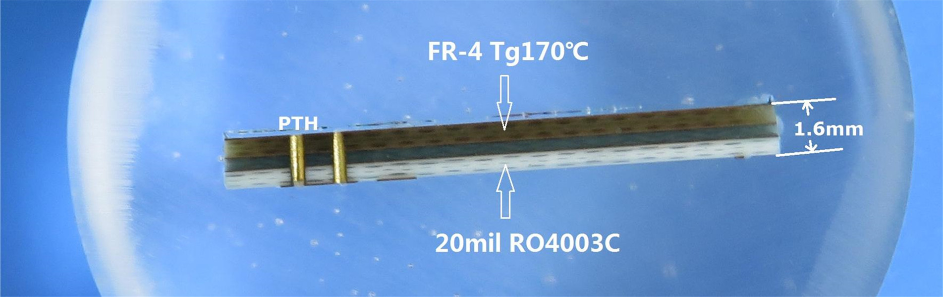
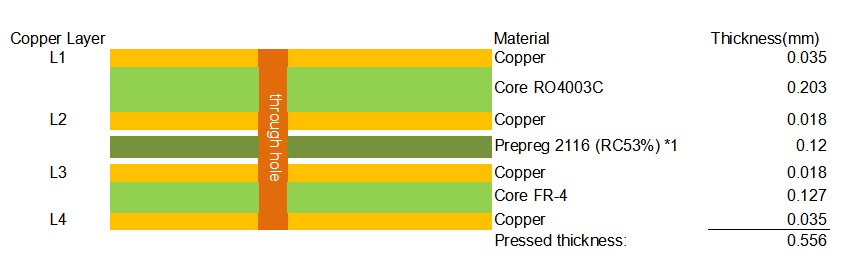
In this build, an 8 mil (0.203 mm) Rogers RO4003C core sits under the top layer, bonded through the inner layers to a Tg170 FR-4 core at the bottom, with one sheet of 2116 prepreg (53% resin content) joining the two. The finished board is 0.556 mm — about 21.9 mil — with 1 oz finished copper (35 µm) on the outer layers and 0.5 oz (18 µm) on the inner layers.
From top to bottom: L1 is the outer RF layer, L1–L2 is the 8 mil RO4003C core, L2 is an inner copper plane, the 2116 prepreg bonds L2 to L3, L3–L4 is a 5 mil (0.127 mm) FR-4 core, and L4 is the bottom layer. The thickness arithmetic is fixed: 0.450 mm of dielectric plus 0.106 mm of copper equals 0.556 mm. There is no exotic material and no sequential lamination, but it is not a symmetric board — a detail that matters later.
The reason for hybrid construction is electrical. RO4003C is a woven-glass-reinforced hydrocarbon/ceramic laminate with a process dielectric constant of 3.38 ± 0.05 at 10 GHz and a design Dk of 3.55 across 8–40 GHz. Its dissipation factor is 0.0027 at 10 GHz and 0.0021 at 2.5 GHz. A standard FR-4 epoxy system typically shows a Dk near 4.3–4.5 with a much wider tolerance and a dissipation factor around 0.015–0.020 — roughly 5.5 to 7 times higher.
That difference matters in two ways. Dielectric loss converts directly into signal attenuation, so a 50 Ω microstrip on FR-4 loses noticeably more energy per centimetre at microwave frequencies — the reason power amplifiers and receive paths are rarely designed on it above a few hundred MHz. The tighter Dk tolerance also keeps controlled-impedance lines closer to target across production. On the 8 mil core, a 50 Ω microstrip at 1 oz copper needs only about 0.38 mm (15 mil) of trace width, a geometry any normal shop can hold.
RogersRO4003C also holds its dielectric constant across conditions. Its thermal coefficient of Dk is +40 ppm/°C from −50 to 150 °C, so a 200 °C swing shifts Dk by less than 1%, and the design Dk stays flat across 8–40 GHz. Filters and matching networks remain centred rather than drifting with the weather.
It is tempting to read “FR-4” as merely the cheap part, but it does real work. The layers below L2 mostly carry power distribution, control logic and digital returns that do not benefit from a 3.38 Dk dielectric. Using FR-4 there keeps panel cost closer to a conventional multilayer board while adding the dielectric thickness needed for the 0.556 mm target.
The grade matters: Tg170 FR-4 has a glass transition temperature of 170 °C, comfortably above the peak temperatures of lead-free reflow. It is qualified to survive multiple lead-free reflow cycles without the resin softening or the interlayer delamination that lower-Tg boards can develop in assemblies with dense SMT on both sides. The hybrid board therefore moves through the same assembly process as a standard FR-4 product, with the same handling and fixturing.
A manufacturing point is often overlooked. Unlike PTFE-based high-frequency laminates, RO4003C is a rigid, thermoset material processed on ordinary FR-4 equipment — no sodium etch, no specialised via preparation — and it conforms to IPC-4103 slash sheet /10. A hybrid of RO4003C and FR-4 is consequently a practical combination: both materials share the same production line.
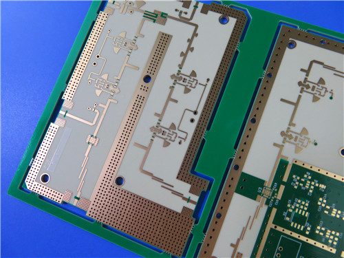
A hybrid stack is not free, and its failure modes are predictable. The most important is thermal expansion.RO4003Csubstrate expands at 11 and 14 ppm/°C in the X and Y axes — close to copper — with a 46 ppm/°C Z-axis value. The FR-4 members respond differently to heat, and this stack is mechanically asymmetric: 0.203 mm of ceramic core on one side and 0.127 mm of FR-4 on the other. Run the materials through a standard FR-4 press cycle and the mismatch can appear as bow or twist, or as delamination at the inner-layer interface.
That is why hybrid construction lives or dies on the press profile rather than the datasheet. A controlled ramp, dwell and cooling sequence under defined pressure, with lay-up and resin-content control for the prepreg, lets the two cores move together through the glass transition, and the low Z-axis CTE of RO4003C then supports plated through-hole reliability under thermal shock. These are mature processes, but they require a shop that runs mixed-dielectric boards routinely — worth verifying before an order rather than after the first warped lot arrives.
Two limitations should be stated plainly. RO4003C is non-brominated and is not UL 94 V-0 rated; if the end product requires a V-0 flame rating, the flame-retardant sister grade RO4350B is the specified alternative. And its low-loss advantage matters only above the frequencies where FR-4 loss becomes a problem — at low digital speeds, a hybrid adds cost without benefit.
The 4-layer hybrid PCB fits when a board genuinely combines RF with conventional circuitry:
· Cellular base-station antennas and power amplifiers
· RF front-end modules that combine microwave paths with digital control
· RFID reader boards and antenna structures
· Automotive radar and sensor front ends
· Low-noise block downconverters for satellite reception
RO4003C’s published low-outgassing results — 0.06% total mass loss under NASA SP-R-0022A — also support space-adjacent uses. The construction is the wrong choice in three situations: when every layer is RF (an all-Rogers stack is simpler), when the board is purely low-speed digital (FR-4 is sufficient), and when a mandatory V-0 flame rating applies (specify RO4350B or RO4835).
If you specify this hybrid, the procurement record should be explicit: the exact core and prepreg gauges (8 mil RO4003C, 2116 prepreg at 53% resin content, 5 mil Tg170 FR-4), the outer and inner copper weights, the finished-thickness tolerance, the surface finish, and 100% electrical test. Confirming that the fabricator holds a qualified hybrid press profile — rather than assuming the FR-4 recipe applies — is the single step that prevents most field problems.
So, is a 4-layer 8mil RO4003C Tg170 FR-4 hybrid PCB right for you?
If your design contains a genuine RF layer that needs controlled impedance and low loss alongside conventional circuitry, and you are prepared to specify the stack precisely and work with a shop qualified for mixed-dielectric lamination, it is a well-supported middle ground: better performance than FR-4, lower cost than an all-Rogers board. If any of those conditions is missing, the simpler material is usually the correct one.
Categories
New Blog
Tags
 6-11C Shidai Jingyuan, Fuyong, Baoan, Shenzhen, Guangdong, China 518103


For inquiries about our products or pricelist, please leave to us and we will be in touch within 24 hours.
© Copyright: 2026 Shenzhen Bicheng Electronics Technology Co., Ltd.. All Rights Reserved.

IPv6 network supported


