
 Call Us Now !
Tel : +86 755 27374946
 Order Online Now !
Email : info@bichengpcb.com
Why Use Tg170 TU-768 FR-4 Cores in a 10-Layer RO4350B Hybrid PCB?
Why Use Tg170 TU-768 FR-4 Cores in a 10-Layer RO4350B Hybrid PCB?
When a 10-layer RF module is quoted as a pure ceramic build, the bill of materials can look unreasonable for a volume product. The better engineering response is to ask which layers actually need the high-frequency dielectric. In a 10-layer RO4350B + TU-768 hybrid PCB, the two outer-facing cores use10 mil (0.25 mm) RO4350B hydrocarbon ceramic laminate, while the three inner cores are built from TU-768, a Tg 170 °C high-reliability FR-4. The RF performance stays on the surfaces where the signals live, while the inner material budget goes to thermal endurance, structural stiffness and flatness. This article examines the cost and thermal logic using published data from both laminates.
Which layers in an RF module actually carry microwave energy?
Controlled-impedance RF lines on a conventional multilayer board are almost always outer-layer structures: microstrip lines on the top and bottom copper, referenced to nearby planes. The inner layers of a typical RF front-end module do a different job: ground planes, power distribution, bias and control nets, switching regulator traces and low-speed digital housekeeping. These nets do not run at gigahertz, and their impedance does not depend on a dielectric constant of 3.48.
The hybrid principle follows directly from that division of labour. Specify the low-loss ceramic for the two cores that form the outer copper pairs, and specify a qualified high-Tg FR-4 for the three cores that form the inner pairs. In a 10-layer stack, six of the ten copper layers sit on TU-768 cores, while the remaining four sit on RO4350B. Every microwave-facing line is still on the ceramic, so the RF specification is not a compromise; it is a placement decision.
The cost logic: pay for ceramic only where the field is
A ten-layer build contains five cores, four prepreg pairs and ten copper layers. In an all-ceramic version, all five cores would be RO4350B; in the hybrid, only two are. The saving is therefore structural rather than the result of a price negotiation.
RO4350B is a specialty hydrocarbon ceramic laminate with a published process dielectric constant of 3.48 ± 0.05 at 10 GHz and a dissipation factor of 0.0037. TU-768 is a high-volume, qualified FR-4 produced in a wide range of glass styles and in core thicknesses from 0.002 to 0.062 inches. High-volume FR-4 and specialty microwave laminates belong to different cost categories, and moving three of the five cores — six of ten copper layers — into the FR-4 category is where the material bill comes down. Because RO4350B is a non-PTFE ceramic that processes on standard FR-4 lines, no sodium etch or separate fabrication line is needed.
For a program that ships in volume, that is the difference between a ceramic board that is technically correct and one that is commercially viable — provided the RF content genuinely sits on the outer layers.
Can TU-768 survive lead-free assembly? Follow the thermal data?
The natural objection is reliability: can an FR-4 core survive double-sided lead-free reflow? TU-768 is not a generic FR-4. Its glass transition temperature is 170 °C by TMA (180 °C by DSC, 190 °C by DMA), and its decomposition temperature is 350 °C. The TUC data sheet reports a 288 °C solder-float survival above 60 seconds, a T288 time above 15 minutes and a T300 time above 2 minutes. These numbers describe how long a board can sit at a given temperature before the polymer breaks down. A lead-free reflow peak typically reaches 245–260 °C for seconds, and a double-sided board sees that peak twice; a 15-minute T288 margin leaves a wide safety gap.
The laminate is qualified to IPC-4101E /126 with QPL certification, carries a UL 94 V-0 rating under file E189572, and is explicitly lead-free compatible. One boundary applies: its maximum operating temperature is 130 °C, so it is not the right substrate for continuous high-temperature environments.
Table 1. Selected TU-768 properties versus IPC-4101 /126 requirements (source: TUC data sheet DS1801007A).
|
Property |
Typical value (TU-768) |
IPC-4101 /126 requirement |
|
Tg, TMA (DMA / DSC) |
170 °C (190 / 180 °C) |
> 170 °C |
|
Td, TGA |
350 °C |
> 340 °C |
|
Solder float at 288 °C |
> 60 s |
> 10 s |
|
T260 |
> 60 min |
> 30 min |
|
T288 |
> 15 min |
> 15 min |
|
T300 |
> 2 min |
> 2 min |
|
CTE, x / y axis |
11–15 ppm/°C |
N/A |
|
CTE, z axis (total) |
2.7% |
< 3.0% |
|
Water absorption |
0.18% |
< 0.8% |
|
Flammability |
94V-0 |
94V-0 |
Why a 2.5 mm mixed stack stays flat?
The second objection is warpage. A 10-layer PCB, 2.5 mm panel built from two resin systems would be a warpage risk if the materials were poorly matched; the published CTE data explain why the pairing works. TU-768 expands at 11–15 ppm/°C in the x and y axes; RO4350B is listed at 10 and 12 ppm/°C. They move almost identically in the plane of the board, so the ceramic skins and FR-4 cores do not fight each other through pressing and reflow. Through the thickness, TU-768 is specified at 2.7% total z-axis expansion against an IPC limit of 3.0%, while RO4350B lists 32 ppm/°C; both are designed to protect plated-through-hole reliability.
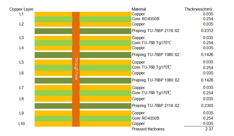
The mechanical side matters just as much at 2.5 mm. TU-768 lists a Young's modulus of 25 / 22 GPa in the warp and fill directions, versus 16.8 / 14.2 GPa for RO4350B, with flexural strength above 60,000 psi lengthwise. The stiffer FR-4 cores form the structural backbone, and the stack is mirrored around its centre — heavier 2116 prepreg pairs near the outer cores and 1080 pairs in the middle. In-plane CTE matching and symmetry — not any single material — are what hold a mixed-dielectric board flat. The remaining process work sits in the press cycle: gradient heating and controlled cooling accommodate the two z-axis behaviours.
When the hybrid is the wrong choice?
The hybrid is a placement decision, not a licence to replace ceramic everywhere. With a dielectric constant around 4.3 and a loss factor of 0.023 at 10 GHz — roughly six times RO4350B's 0.0037 — TU-768 is not a microwave dielectric. If inner layers carry RF, high-speed differential pairs or mmWave structures, those layers should stay on ceramic or low-loss PTFE. The hybrid pays off only when the high-frequency content is concentrated on controlled-impedance outer layers and the inner layers are power, ground, control and digital. The same caution applies to temperature: boards that must run above 130 °C continuously are outside the TU-768 rating. A credible fabricator states these boundaries rather than presenting the hybrid as a universal saving.
What to ask before accepting a hybrid quote?
A few questions separate a real engineered hybrid from a paper saving:
· Ask for the named laminate and prepreg, not an unnamed generic TG170 FR-4.
· Ask for the published Tg, Td and T288 data, and the IPC-4101 slash sheet.
· Ask for the actual layer assignments, showing every RF line on the ceramic.
· Ask for stack symmetry, the press profile and the acceptance standard; this build is made to IPC-6012D Class 3 with 25 μm plated-hole copper and 100% electrical test.
· Ask for the panel warpage limit, including the measurement method.
A fabricator that answers all of these has engineered the hybrid, not relabeled a downgrade.
Conclusion
The hybrid answers a precise engineering question: how to keep microwave performance on the outer RF layers without paying for five cores of ceramic. Six of the ten copper layers move to TU-768, a Tg 170 °C FR-4 whose T288, solder-float and CTE data show it can survive repeated lead-free assembly, whose x/y CTE of 11–15 ppm/°C is effectively matched to RO4350B's 10/12 ppm/°C, and whose higher modulus provides the stiffness a 2.5 mm panel needs. The premium dielectric stays where the RF field is; the workhorse FR-4 carries the thermal and mechanical load where RF is not routed. That is not a downgrade. It is the disciplined way to design a cost-optimized RF board for volume production.
Data sources: Rogers Corporation, RO4000 Series RO4003C / RO4350B Data Sheet, Pub# 92-004 (rev. 08/03/2022); Taiwan Union Technology, TU-768 / TU-768P Laminate and Prepreg, DS1801007A.
Categories
New Blog
Tags
 6-11C Shidai Jingyuan, Fuyong, Baoan, Shenzhen, Guangdong, China 518103


For inquiries about our products or pricelist, please leave to us and we will be in touch within 24 hours.
© Copyright: 2026 Shenzhen Bicheng Electronics Technology Co., Ltd.. All Rights Reserved.

IPv6 network supported


