
 Call Us Now !
Tel : +86 755 27374946
Call Us Now !
Tel : +86 755 27374946
 Order Online Now !
Email : info@bichengpcb.com
Order Online Now !
Email : info@bichengpcb.com
Dk 3.0 or Dk 10.2: Which High-Frequency Substrate Fits Your Antenna Design?
Dk 3.0 or Dk 10.2: Which High-Frequency Substrate Fits Your Antenna Design?
Quick Answer
Choose Dk 3.0 for wider traces, easier impedance control, and higher-frequency operation where dispersion matters. Choose Dk 10.2 for circuit miniaturization, compact antenna spacing, or high-Dk architectures. TFA1020, a PTFE-ceramic composite with no glass fiber, delivers Dk 10.2 at 10 GHz with Df as low as 0.0015 and CTE matched to copper, making high-Dk performance viable without the signal integrity penalties of glass-reinforced substrates.
Key Takeaways
· Dk 3.0 offers wider traces and easier impedance control; Dk 10.2 enables compact layouts and smaller antenna elements.
· TFA1020 (Dk 10.2) uses a PTFE-ceramic composite with no glass fiber cloth, eliminating the fiberglass effect that causes signal skew.
· TFA1020's Df of 0.0015 at 10 GHz (0.0017 at 20 GHz) keeps loss low at high Dk, with CTE of 16 ppm/°C matching copper across -55°C to 288°C.
· High Dk narrows traces for a given impedance, increasing tolerance sensitivity—verify your fab's 4/6 mil capability before committing.
· A 2-layer TFA1020 PCB at 0.25 mm with 1 oz copper and pure gold finish is manufacturable with standard processes by an experienced PTFE shop.
Why Dk Choice Makes or Breaks Your Antenna Design
Dielectric constant determines trace width for a target impedance, antenna element dimensions, and the physical size of your entire RF front end. A Dk 3.0 substrate yields roughly 1.8 times wider 50-ohm microstrip traces than Dk 10.2, meaning more forgiving etching tolerances and lower conductor loss. But patch antennas scale inversely with the square root of Dk, so a Dk 10.2 board can be nearly half the size of an equivalent Dk 3.0 design. Higher Dk substrates also tend to show greater frequency dispersion and, in glass-reinforced materials, more weave-induced Dk variation. The Dk decision must account for not just the nominal value, but how uniformly it is maintained across the board and over temperature.
TFA1020: A Dk 10.2 Substrate Without Glass Fiber
Most high-frequency PCBs use resin impregnated into woven glass fiber cloth. At microwave frequencies, this weave creates periodic Dk variations across the board, known as the fiberglass effect, causing signal skew and impedance inconsistency. Wangling TFA1020 takes a different approach: its dielectric consists of PTFE resin mixed with uniformly dispersed nano-ceramic particles, with no glass fiber cloth at all. The result is a homogeneous dielectric with minimal X/Y/Z anisotropy, meaning electrical and mechanical properties are nearly identical regardless of direction—critical for phased arrays where element-to-element phase consistency directly determines performance.
What the Technical Data Means for Your Selection
A common concern with high-Dk substrates is elevated loss.TFA1020 PCB's dissipation factor of 0.0015 at 10 GHz, rising only to 0.0017 at 20 GHz, addresses this directly: lower Df means less substrate heat in power amplifier stages and more power to the antenna, while Df flatness from 10 to 20 GHz keeps insertion loss predictable for wideband satellite modules. The temperature coefficient of Dk (TCDK) is -340 ppm/°C over -55°C to 150°C, modest and consistent enough for drift compensation. Thermal expansion: X/Y-axis CTE of 16 ppm/°C and Z-axis 30 ppm/°C (-55°C to 288°C) closely match copper foil (~17 ppm/°C), minimizing differential expansion and barrel cracking in plated through-holes. Thermal conductivity of 0.88 W/m·K exceeds standard FR-4, and combined with UL 94 V-0 and 0.015% moisture absorption, TFA1020 meets aerospace robustness expectations.
Manufacturing Realities: Can You Actually Build It?
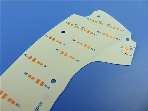
A 2-layer rigid PCB on a 0.127 mm (5 mil) TFA1020 core illustrates manufacturability. Finished thickness is 0.25 mm, with 1 oz (35 μm) copper. Minimum trace/space is 4/6 mils, on 1 oz copper, and minimum drilled hole is 0.35 mm with via plating at 20 μm. No blind vias required. The surface finish is pure gold, for microwave contact. Every board undergoes 100% electrical test. TFA1020 does not require exotic processes: a PTFE manufacturer can produce it with standard lamination, drilling, etching, plating. Before committing, confirm your fabricator can hold 4/6 mil trace/space on 1 oz copper.
Where Dk 10.2 Wins: Application Scenarios
High Dk is not universally better, but it delivers clear advantages in specific cases. Phased array antennas and beamforming networks benefit from both the compact element spacing that Dk 10.2 enables and the fiberglass-effect elimination that TFA1020 provides: thousands of elements must maintain consistent phase relationships, and any substrate-induced variation degrades beam accuracy. Microwave circuits and phase-sensitive antennas leverage Dk 10.2 to reduce dimensions. Aerospace systems, early warning radars, airborne radars, satellite communications, and navigation systems fit naturally.
TFA Series: The Full Dk Spectrum for Your Selection
Engineers evaluating TFA1020 should map requirements against the full series. TFA294 (Dk 2.94) and TFA300 (Dk 3.0) suit general microwave circuits where wider traces and easier impedance control are desired, or at higher frequencies where dispersion is a concern. TFA615 (Dk 6.15) offers moderate miniaturization. TFA1020 (Dk 10.2) is the right choice when priorities include maximum circuit miniaturization or compact antenna spacing. All grades share the same no-glass-fiber construction.
Frequently Asked Questions
Q1: How do I decide between Dk 3.0 and Dk 10.2 for my antenna?
Startwith your size constraint and frequency. If board area is tight or you need dense antenna spacing, Dk 10.2 (TFA1020) reduces dimensions significantly. If you operate above ~20 GHz, need wider traces for yield, or want maximum impedance margin, Dk 3.0 (TFA300) is safer. Verify your fabricator's trace/space capability at your chosen copper weight before finalizing.
Q2: Does a higher Dk substrate always have higher loss?
Not necessarily. Loss depends on dissipation factor (Df), not Dk alone. TFA1020 achieves Dk 10.2 with Df of 0.0015 at 10 GHz, comparable to or better than many lower-Dk glass-reinforced substrates. The PTFE-ceramic composition makes low loss at high Dk possible.
Q3: Does TFA1020 contain glass fiber cloth?
No. The dielectric is PTFE resin with uniformly dispersed nano-ceramic particles and no glass fiber reinforcement. This eliminates the fiberglass weave effect that causes signal skew and impedance variations in conventional substrates, especially valuable for phase-sensitive arrays.
Q4: Can TFA1020 be manufactured with standard PCB processes?
Yes. Standard lamination, drilling, etching, and plating workflows apply, provided the manufacturer has PTFE substrate experience. A 2-layer board with 0.25 mm thickness, 1 oz copper, and 4/6 mil trace/space is within standard production capabilities. Confirm yield data for your specific trace width before volume production.
Q5: What is the maximum operating temperature for TFA1020?
Key properties are specified over wide ranges: TCDK from -55°C to 150°C, CTE from -55°C to 288°C. The material withstands standard assembly including lead-free reflow (~260°C peak). For long-term continuous operation, consult the supplier's guidelines, as thermal cycling frequency and stress influence reliability.
Conclusion
The Dk 3.0 versus Dk 10.2 decision comes down to a clear trade-off: Dk 3.0 offers wider traces, easier impedance control, and better high-frequency dispersion behavior, while Dk 10.2 delivers substantial miniaturization and denser antenna integration. TFA1020 makes the high-Dk choice viable by pairing Dk 10.2 with a no-glass-fiber PTFE-ceramic dielectric, Df as low as 0.0015, CTE matched to copper, and aerospace-grade robustness. Manufacturable with standard processes, TFA1020 is worth evaluating whenever size, phase consistency, and reliability are non-negotiable in your high-frequency antenna design.
Categories
New Blog
Tags
 6-11C Shidai Jingyuan, Fuyong, Baoan, Shenzhen, Guangdong, China 518103


For inquiries about our products or pricelist, please leave to us and we will be in touch within 24 hours.
© Copyright: 2026 Shenzhen Bicheng Electronics Technology Co., Ltd.. All Rights Reserved.

IPv6 network supported


