
 Call Us Now !
Tel : +86 755 27374946
Call Us Now !
Tel : +86 755 27374946
 Order Online Now !
Email : info@bichengpcb.com
Order Online Now !
Email : info@bichengpcb.com
What Benefits Does a CuClad 250 PCB Bring to High-Frequency Circuit Design?
What Benefits Does a CuClad 250 PCB Bring to High-Frequency Circuit Design?
1.Introduction
High-frequency circuit design demands substrate materials that can maintain signal integrity across microwave and millimeter-wave bands. Among the various PTFE-based laminates available, Rogers CuClad 250 has established itself as a reliable option for engineers balancing electrical performance with mechanical robustness. Unlike pure PTFE substrates that can suffer from dimensional instability, CuClad 250 incorporates a cross-plied woven fiberglass reinforcement that bridges the gap between high-frequency performance and conventional PCB manufacturability.
For design teams working on radar frontends, microwave filters, or low-noise amplifiers (LNAs), selecting the right laminate directly impacts insertion loss, phase consistency, and long-term reliability. This article breaks down the material science behind CuClad 250, presents measured performance data, and walks through a real-world 2-layer board specification to illustrate how these properties translate into practical design outcomes.
2. Quick Answer
A CuClad 250 PCB delivers stable dielectric performance (Dk 2.40–2.55 at 10 GHz) with extremely low dissipation factor (0.0017), making it well-suited for microwave and radar applications where signal loss must be minimized. Its cross-plied woven fiberglass construction improves dimensional stability and mechanical strength compared to non-woven alternatives, while maintaining the low-loss characteristics expected from PTFE composites. The material supports standard PCB fabrication processes including immersion gold surface finish and 100% electrical testing, enabling production-grade high-frequency boards with IPC-Class-2 quality standards.
3.Key Takeaways
1) Consistent low Dk across frequencies: CuClad 250 maintains a dielectric constant of 2.40 to 2.55 from 1 MHz through 10 GHz, supporting wider transmission line widths and lower insertion loss for impedance-controlled designs.
2) Superior mechanical balance: Cross-plied fiberglass orientation (alternating 90°plies) delivers balanced electrical and mechanical properties in both X and Y axes, reducing warpage and improving dimensional stability.
3) Low loss for high-frequency bands: A dissipation factor of 0.0017 at 10 GHz ensures minimal signal attenuation, critical for radar, ECM, and ESM systems operating at microwave frequencies.
4) Environmental resilience: With 0.03% moisture absorption and near-zero outgassing (TML 0.01%, CVCM 0.0%), the material performs reliably in humid and vacuum environments.
5) Manufacturing compatibility: CuClad 250 supports standard PCB processing including 0.3 mm minimum drill sizes, 4/6 mil trace/space, and immersion gold surface finish, with IPC-Class-2 quality achievable in volume production.
4.Understanding CuClad 250 Material Composition
Rogers CuClad 250 is a composite laminate consisting of polytetrafluoroethylene (PTFE) resin reinforced with cross-plied woven fiberglass fabric. What distinguishes it from many other high-frequency substrates is its higher fiberglass-to-PTFE ratio, which shifts the material's mechanical profile closer to that of conventional FR-4 substrates while preserving the electrical benefits of PTFE.
The cross-plied construction means that alternating fiberglass plies are oriented at 90 degrees to each other. This layup strategy creates isotropic-like behavior in the planar directions. For designers, this translates to more predictable dielectric constant uniformity across the board area and reduced risk of skewed impedance values depending on trace orientation—a common concern with non-woven or unidirectionally reinforced PTFE laminates.
A standard 2-layer CuClad 250 stackup uses a 0.254 mm (10 mil) core with 35μm (1 oz) copper cladding on both sides. This configuration is particularly common for microwave component boards where controlled impedance and minimal dielectric thickness variation are required.
5. Core Electrical Properties and Performance Data
5.1 Dielectric Constant Uniformity
The dielectric constant (Dk) of CuClad 250 ranges from 2.40 to 2.55, measured at both 1 MHz and 10 GHz. This tight tolerance is significant for two reasons. First, a lower Dk allows designers to use wider transmission lines for a given target impedance—typically 50 ohms in RF systems—which reduces conductor loss and eases manufacturing tolerances. For example, on a 10 mil thick CuClad 250 core, a 50-ohm microstrip line can be approximately 27 mils wide, compared to roughly 18 mils on a Dk 3.5 substrate. Wider traces are easier to etch consistently and suffer less from skin-effect losses at high frequencies.
Second, the stability of Dk across frequency bands ensures that impedance and phase response remain predictable as operating frequencies scale up. This is especially valuable for broadband components such as directional couplers and multi-octave filters.
5.2 Dissipation Factor and Insertion Loss
With a dissipation factor (Df) of just 0.0017 at 10 GHz, CuClad 250 ranks among the lower-loss commercially available PCB materials. To put this in perspective: conventional FR-4 materials typically exhibit Df values between 0.02 and 0.025 at similar frequencies, meaning CuClad 250 reduces dielectric loss by over an order of magnitude. For a 10 cm transmission line at 10 GHz, this difference can translate to several decibels of saved signal power—often the margin between meeting or failing system noise figure requirements.
5.3 Peel Strength
Copper peel strength of 14 lbs/in indicates robust adhesion between the copper foil and the PTFE-fiberglass substrate. This is an important reliability metric, particularly for boards that undergo thermal cycling or operate in mechanically demanding environments. Higher peel strength reduces the risk of trace lifting during assembly reflow or field operation.
6.Mechanical and Environmental Reliability
6.1 Dimensional Stability
The cross-plied woven fiberglass structure gives CuClad 250 better dimensional stability and lower thermal expansion in all directions compared to non-woven PTFE laminates. For PCB fabricators, this means tighter registration tolerance between layers and more predictable etch factor. For end users, it translates to consistent board dimensions across temperature excursions, which matters for antenna arrays and phased array radar systems where element spacing directly affects beam steering accuracy.
6.2 Moisture Absorption
At 0.03% moisture absorption, CuClad 250 is highly resistant to humidity-induced performance drift. Because water has a much higher dielectric constant (~80), even small amounts of absorbed moisture can measurably shift a substrate's effective Dk and increase loss. The 0.03% figure ensures that boards deployed in outdoor or high-humidity environments maintain their designed electrical characteristics without extensive conformal coating requirements.
6.3 Outgassing Performance
For aerospace and vacuum applications, outgassing is a critical selection criterion. CuClad 250 reports a Total Mass Loss (TML) of just 0.01%, Collected Volatile Condensable Material (CVCM) of 0.0%, and 0% Water Vapor Regain (WVR). These values meet or exceed typical space-grade material requirements, making the laminate suitable for satellite communications payloads and high-vacuum test equipment.
7. Real-World Application: 2-Layer CuClad 250 PCB Specification
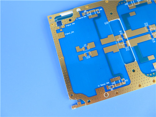
To illustrate how these material properties translate into a production board, consider a recently fabricated2-layer rigid CuClad 250 PCB designed for a microwave subsystem.
7.1 Board Profile
7.2 Fabrication Standards
This particular board demonstrates several practical points. First, the 0.4 mm finished thickness (10 mil core + two copper layers) supports compact microwave assemblies where board height is constrained. Second, the use of immersion gold surface finish provides excellent RF contact performance and solderability for both SMT and through-hole components. Third, despite being a high-frequency PTFE-based material, CuClad 250 supports standard 0.3 mm drill sizes and 4/6 mil trace geometries—no specialized fabrication equipment is required beyond what a standard PCB shop already operates.
The absence of blind vias and the use of a simple 2-layer stackup also keep costs manageable, making CuClad 250 accessible for both prototyping and mid-volume production runs. Worldwide availability further supports global supply chains for OEMs building radar, electronic countermeasure (ECM), and electronic support measure (ESM) systems.
Typical Applications and Use Cases
CuClad 250 high frequency PCBs find their strongest fit in applications where low loss and dielectric consistency directly determine system performance:
FAQ
Q1: How does CuClad 250 compare to RO4000 series materials for high-frequency designs?
CuClad 250 generally offers a lower Dk (2.4–2.55 vs. ~3.5 for RO4003C) and lower dissipation factor, resulting in wider transmission lines and lower dielectric loss. RO4000 series materials often provide higher glass transition temperature and may be preferred for higher-power or higher-temperature applications. The choice depends on whether the design prioritizes lowest possible loss or thermal robustness.
Q2: Can CuClad 250 PCBs be fabricated using standard FR-4 manufacturing processes?
Yes, for the most part. CuClad 250 supports standard drilling, etching, and plating processes. The 0.3 mm minimum hole size and 4/6 mil trace/space achievable on CuClad 250 align with standard PCB shop capabilities. However, PTFE-based materials do require specific surface preparation for plating adhesion, and experienced high-frequency PCB fabricators typically have established processes for these materials.
Q3: What is the typical impedance tolerance for CuClad 250 microstrip lines?
With controlled dielectric thickness and consistent Dk uniformity, impedance tolerances of±10% are standard, and±5% is achievable with tight process controls. The cross-plied fiberglass structure helps reduce Dk variation across the panel, contributing to more consistent impedance values compared to non-woven PTFE substrates.
Q4: Is CuClad 250 suitable for multilayer PCB designs?
While CuClad 250 is most commonly used in 2-layer configurations for simple microwave circuits, it can be incorporated into multilayer stackups when bonded with appropriate prepreg materials. However, multilayer designs with PTFE cores require careful material matching and lamination process control. For complex multilayer high-frequency designs, consulting with the PCB fabricator early in the design phase is recommended.
Conclusion
CuClad 250 occupies a valuable niche in the high-frequency PCB material landscape, combining the low-loss electrical performance of PTFE with the mechanical reliability of woven fiberglass reinforcement. Its Dk of 2.40–2.55 at 10 GHz, dissipation factor of 0.0017, and strong peel strength make it a practical choice for microwave components, radar frontends, and aerospace systems where both signal integrity and mechanical durability matter.
The real-world 2-layer board example demonstrates that these material properties translate directly into producible designs—supporting standard feature sizes, immersion gold surface finish, and IPC-Class-2 quality standards without requiring exotic fabrication techniques. For design engineers evaluating substrate options for their next high-frequency project, CuClad 250 deserves consideration as a balanced, production-ready material that does not force a tradeoff between electrical performance and manufacturability.
Categories
New Blog
Tags
 6-11C Shidai Jingyuan, Fuyong, Baoan, Shenzhen, Guangdong, China 518103


For inquiries about our products or pricelist, please leave to us and we will be in touch within 24 hours.
© Copyright: 2026 Shenzhen Bicheng Electronics Technology Co., Ltd.. All Rights Reserved.

IPv6 network supported


