Rogers RT/duroid 6006 and 6010.2LM PCB
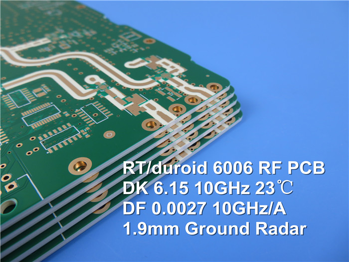
PCB material is primarily used in electronic and microwave circuits. Its performance has a significant impact on the circuit system's signal transmission speed, energy loss, and characteristic impedance. Rogers Corporation, a well-known material supplier, has introduced RT/duroid 6006 and 6010.2LM, a high performance microwave PCB material. It is made of ceramic-polytetrafluoroethylene (PTFE) composite with a dielectric constant of 6.15, and it is primarily used in high-frequency circuit applications.
RT/duroid 6006 PCB has a strictly controlled dielectric constant, thickness, low hygroscopicity, and excellent thermomechanical stability. It has a simple manufacturing process and can maintain high stability in long-term use. When ordering the RT/duroid 6006, users can specify the thickness of the PCB material as well as the weight of the copper foil. Rogers offers two-sided thicknesses ranging from 1/2 oz. to 2 oz. /ft2 (18 to 70) for RT/duroid 6006 microwave PCB materials u M) Standard or reverse-treated electroplated copper clad, with thick aluminium, brass, or copper based metal sheets available for customization. RT/duroid 6006 has the following standard tolerance media thicknesses: 0.010, 0.025, 0.050, 0.075", and 0.100". (0.254, 0.635, 1.270, 1.905, 2.54mm)
RT/duroid 6006 microwave PCB material can be used in the following fields: patch antenna, satellite communication system, power amplifier, aircraft anti-collision system, ground-based radar early warning system.

Features and advantages of RT/duroid 6006:
A dielectric constant of up to 6.15 helps reduce circuit size
Ideal for low loss, X band and below
Strictly controlled thickness and dielectric constant tolerances for circuits requiring high repeatability
Product specifications for RT/duroid 6006
Standard thickness, 0.005 (0.127 mm). 0.010 (0.254 mm), 0.025 (0.635 mm), 0.050 (1.27 mm), 0.075 (1.90 mm), 0.100 (2.50 mm)
Standard panel dimensions for RT/duroid 6006:
10'X 10" (254 X 254 mm). 10 "X 20" (254 X 508 mm). 20 "X 20" (508 X 508 mm) - Nonstandard, 18 "X 12" (457 X 305 mm), 18 "X 24" (457 X610 mm) - Nonstandard
Standard copper clad thickness for RT/duroid 6006
1/2 oz. (18) u M), 1 oz. (35) u M), 2 oz. (70) L M)
RT / Duroid 6006: microwave circuit board and high frequency laminate
RT / Duroid 6006 application:
Locomotive, rail transit, electric power, renewable energy, body and chassis, lighting, equipment and inverter power supply, national defense industrial equipment, onboard, onboard communication, onboard entertainment. Internet of vehicles, industrial automation, industrial servo, indoor lighting, smart home, industrial equipment control, mobile phone related, electric vehicle power system, communication equipment, Internet of things, storage, safety system, patch antenna, satellite communication system, power amplifier, aircraft anti-collision system. Ground radar early warning system.
Manufacturing process (6.15) and design (6.15) are the two dielectric constants of RT/duroid 6006 (6.45). For circuit simulation, the design dielectric constant of 6 45 is used.
If the dielectric constant of the bonded sheet is required, RO3006 bonded sheet with a minimum thickness of 5 mil is recommended (0.127 mm). If the dielectric constant of the bonded sheet is not required, it has a thickness of 1.5mil (0.038mm), such as 2929.
Rogers RT/duroid high-frequency circuit materials are PTFE composite PCB materials (including randomly filled glass or ceramic) that are suitable for high-reliability applications like aerospace. The RT/duroid family has long been the most dependable high-reliability PCB material in the industry.
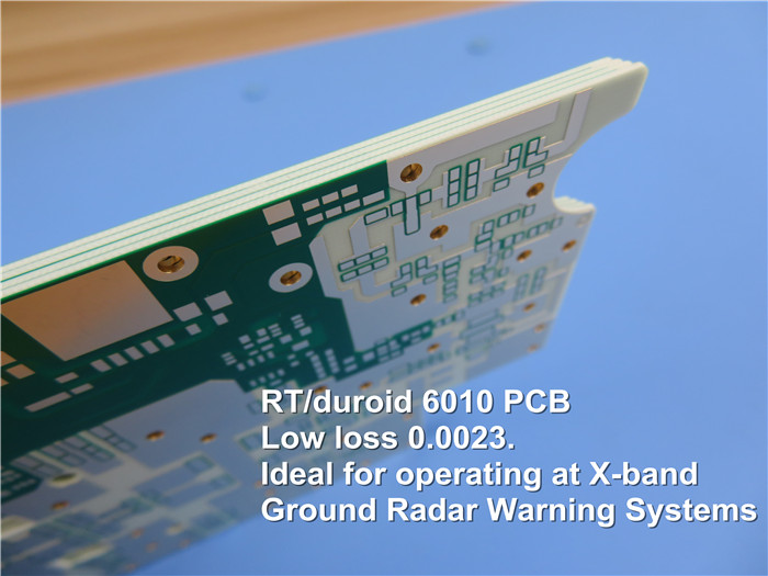
The antenna gain is related to the dielectric loss and copper foil loss of the RT/duroid 6010 PCB material. An increase in both losses will reduce the gain index of the entire antenna. Due to the high frequency, copper foil loss plays a dominant role. For example, there are scratches and stains on the copper foil surface and the dielectric surface, so the scratches on the antenna transmission microstrip line and the dielectric stain at the port will increase the loss and reduce the gain. These are mainly related to the PCB processing process.

The
RT/duroid 6010 PCB material is polytetrafluoroethylene with a small amount of ceramic powder added, and it has a soft texture. If the surface dielectric and copper foil are damaged, the loss of the dielectric and copper foil increases, lowering the antenna gain. To protect the roughness of the dielectric surface after etching, the PCB processing process must prohibit any mechanical grinding or friction on the PTFE dielectric surface after copper foil etching. Chemical cleaning is required after processing to ensure that the surface is stain-free. Confirm the processing of PCBs. To improve antenna yield, the surface roughness of the copper foil and the surface of the dielectric should be protected during the process.
There were three models in Rogers' 6010 series of high-frequency PCB materials. 6010.2LM, 6010.5LM, and 6010.8LM were all discontinued one after the other, and 6010.2LM is now recommended.

 Call Us Now !
Tel : +86 755 27374946
 Order Online Now !
Email : info@bichengpcb.com


