
 Call Us Now !
Tel : +86 755 27374946
Call Us Now !
Tel : +86 755 27374946
 Order Online Now !
Email : info@bichengpcb.com
Order Online Now !
Email : info@bichengpcb.com
Why Choose a 4-Layer 5mil RT6202+FR-4 Hybrid PCB for High-Frequency RF Designs?
Why Choose a 4-Layer 5mil RT6202+FR-4 Hybrid PCB for High-Frequency RF Designs?
When designing RF and microwave circuits above 3 GHz, engineers face a persistent dilemma: standard FR-4 substrates introduce unacceptable signal loss and dielectric instability, while fully Rogers-based multilayer boards carry prohibitive material costs for digital and power sections. A 4-layer 5mil RT6202+FR-4 hybrid PCB offers a pragmatic middle path — placing low-loss Rogers RT/duroid 6202 only where microwave signals travel, and using cost-effective FR-4 for power, ground, and control routing. This article examines when this hybrid construction is the right choice, how it performs against single-material alternatives, and what design and manufacturing factors engineers should evaluate.
FR-4 remains the workhorse of the PCB industry for good reason: it is inexpensive, well-understood, and mechanically robust for digital circuits below approximately 1–2 GHz. However, its electrical performance degrades meaningfully at higher frequencies. At 10 GHz, standard FR-4 exhibits a dissipation factor (tan δ) of roughly 0.022 and a dielectric constant (Dk) around 4.4, with Dk drift exceeding 10% across a −50°C to +150°C temperature range. For 50Ω microstrip lines carrying narrowband radar or communication signals, this level of loss and instability translates directly to reduced link budget, wider beam-squint in phased arrays, and higher bit-error rates.
Additionally, FR-4 post-etch dimensional movement can complicate the tight trace positioning required for antenna arrays and coupled-line structures. While all-FR4 boards remain adequate for low-speed digital and power distribution, they are not an optimal substrate for RF frontends operating in the multi-GHz range — and simply thickening copper or adding layers does not solve the underlying dielectric loss problem.
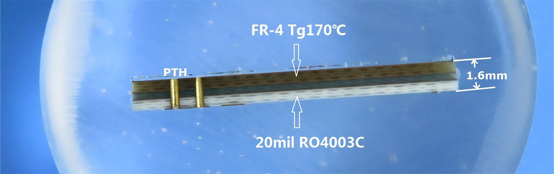
A hybrid PCB combines two or more dielectric materials within a single multilayer stackup, assigning each material to the layers where its properties deliver the most engineering value. In the 4-layer 5mil RT6202+FR-4 configuration, the outer signal layers (L1 and L4) use 5mil (0.127 mm) Rogers RT/duroid 6202 laminate for RF microstrip routing, while the inner layers (L2 and L3) use FR-4 core and prepreg for power planes, ground planes, and low-speed digital control traces.
This segregation is deliberate. RF signals on outer layers benefit from RT6202 controlled Dk of 3.06 ±0.04 at 10 GHz and ultra-low tan δ of 0.0015 — roughly 14 times lower dielectric loss than FR-4 at the same frequency. Meanwhile, inner FR-4 layers provide stable reference planes, power distribution, and interlayer shielding at a fraction of Rogers prepreg cost. The result is a symmetrical stackup with a finished thickness of 1.014 mm, mixed copper weights (1 oz outer, 0.5 oz inner), and consistent impedance control across the board.
The 5mil (0.127 mm) dielectric thickness is the thinnest standard grade of RT/duroid 6202 and is particularly well-suited for hybrid outer-layer construction. At this thickness, 50Ω microstrip lines achieve practical trace widths that balance standard PCB manufacturing capability with desired RF performance. The thin dielectric also keeps the overall board height manageable — critical for compact modules such as 77 GHz automotive radar frontends, GPS receiver hardware, and portable microwave transceivers.
RT6202 thermal coefficient of dielectric constant is only +5 ppm/°C from −50°C to +150°C, ensuring that controlled impedance lines remain within tolerance across the full operating temperature range. Its post-etch dimensional stability of 0.07 mils/inch eliminates the need for double-etching processes to meet tight antenna trace positional tolerances. Copper peel strength of 9.1 lbs/in provides robust adhesion through repeated thermal cycling, an important consideration for IPC-6012 Class 3 high-reliability applications. The material also carries a UL 94 V-0 flammability rating and is fully compatible with lead-free reflow profiles up to its 500°C decomposition temperature.
The table below summarizes how the three construction approaches differ across key engineering criteria. The hybrid approach is not universally superior — it is optimal for a specific class of mixed-signal designs.
|
Criterion |
All-FR4 |
4L RT6202+FR-4 Hybrid |
All-Rogers Multilayer |
|
RF loss at 10 GHz |
High (tan δ ~0.022) |
Low on RF layers (tan δ 0.0015) |
Low throughout |
|
Dk stability over temp |
>10% drift |
Stable on RF layers (+5 ppm/°C) |
Stable throughout |
|
Material cost |
Low |
Moderate |
High |
|
Digital / power routing |
Excellent |
Excellent (FR-4 inner) |
Acceptable but costly |
|
Manufacturing complexity |
Standard |
Moderate (mixed lamination) |
High |
|
Typical target apps |
Digital, low-speed |
Mixed RF-digital modules |
Pure RF / microwave |
For purely digital boards with no RF content, all-FR4 remains the most economical choice. For boards where every layer carries microwave signals — such as pure RF beamforming networks — an all-Rogers stackup may be justified despite the cost. The hybrid construction shines specifically in mixed-signal modules where a portion of the circuitry requires low-loss RF transmission and the remainder is standard digital or power distribution.
Several design practices help engineers extract maximum value from a hybrid 4-layer stackup. First, confine critical RF traces — antenna feeds, power amplifier outputs, low-noise amplifier inputs, and filter networks — to the outer RT6202 layers where loss is lowest. Route these traces as microstrip lines referenced to a solid ground plane on the adjacent FR-4 layer. Avoid running RF traces through vias whenever possible, as each via transition introduces parasitic inductance and a return-path discontinuity.
Second, use the inner FR-4 layers for continuous ground and power planes. The dual inner-plane architecture enhances board capacitance, lowering power supply ripple without additional discrete decoupling components. Third, when vias are unavoidable, specify resin-plugged, electroplated filled vias (via-in-pad) to maintain a flat surface for BGA and fine-pitch mounting, requiring a minimum 75% vertical resin fill per IPC-6012 Class 3. Finally, specify immersion gold (ENIG) surface finish for corrosion resistance, and ensure the fabricator performs 100% AOI, flying probe testing, and cross-section validation on every production lot.
The 4-layer 5mil RT6202+FR-4 hybrid PCB is particularly relevant for the following applications:
· Automotive 77 GHz radar frontends: Compact modules requiring low-loss antenna feed networks alongside digital control and power management on the same substrate.
· Phased array antenna subassemblies: Tight dimensional stability (0.07 mils/inch post-etch) and consistent Dk across temperature ensure predictable beamforming performance.
· GPS and satellite communication receivers: Low-noise RF frontends benefit from minimal dielectric loss, while FR-4 inner layers handle baseband processing and power distribution.
· Portable microwave communication transceivers: The 1.014 mm finished thickness and symmetrical stackup support space-constrained, battery-powered designs with mixed RF-digital content.
In each case, the underlying design principle is the same: route critical RF traces on RT6202 outer layers, reference them to solid ground planes on adjacent FR-4 layers, and use the remaining FR-4 layers for power and digital signals.
Hybrid PCB Board introduce manufacturing considerations that do not apply to single-material boards. The lamination process must accommodate the different CTE profiles of RT6202 (X/Y: 15 ppm/°C, Z: 30 ppm/°C) and FR-4, requiring controlled press profiles to prevent delamination or excessive warpage. The symmetrical 4-layer stackup — RT6202 on both outer layers and FR-4 in the core — helps balance these stresses, but the fabricator must still validate lamination quality through cross-section microscopy on first-article and periodic production samples.
Resin-plugged vias demand strict process control to achieve the minimum 75% vertical fill and 25 µm plating thickness required for IPC-6012 Class 3 compliance. ENIG surface finish provides a flat, solderable surface with excellent corrosion resistance for automotive and aerospace environments. Quality validation should include 100% AOI, flying probe electrical testing, and cross-section microscopy to verify via integrity, interlayer bonding, and void-free lamination. These checks are not optional for Class 3 boards destined for high-reliability applications.
A 4-layer hybrid PCB is a targeted engineering solution, not a universal upgrade. It is the right choice when a design combines multi-GHz RF signal paths with standard digital and power circuitry, and when the cost of an all-Rogers multilayer board cannot be justified for the non-RF portions. By placing RT6202 only on outer RF layers and using FR-4 for inner planes, engineers achieve low-loss, thermally stable microwave performance while controlling material and manufacturing costs.
For engineers evaluating substrate options, the key questions are straightforward: which signal paths genuinely require low-loss dielectric, and can those paths be confined to outer layers? If yes, a hybrid RT6202+FR-4 stackup deserves serious consideration. Partnering with a PCB manufacturer experienced in mixed-material lamination and IPC-6012 Class 3 production ensures the design electrical performance is fully realized in volume manufacturing.
Categories
New Blog
Tags
 6-11C Shidai Jingyuan, Fuyong, Baoan, Shenzhen, Guangdong, China 518103


For inquiries about our products or pricelist, please leave to us and we will be in touch within 24 hours.
© Copyright: 2026 Shenzhen Bicheng Electronics Technology Co., Ltd.. All Rights Reserved.

IPv6 network supported


