

 Call Us Now !
Tel : +86 755 27374946
Call Us Now !
Tel : +86 755 27374946
 Order Online Now !
Email : info@bichengpcb.com
Order Online Now !
Email : info@bichengpcb.com
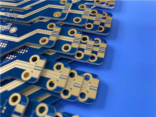
This 4-layer 5mil RT/duroid 6202 + FR-4 hybrid PCB represents a balanced high-reliability solution that bridges high-frequency microwave performance and economical digital circuit integration.
Item NO.:
BIC-606-v691Order(MOQ):
1-10Payment:
T/TProduct Origin:
ChinaShipping Port:
ShenzhenLead Time:
7-10 days
4-layer 5mil RT6202 + FR-4 Hybrid PCB 1.014mm ENIG Resin Plug Vias
1. Product Overview & Core Differentiation
This rigid 4-layer hybrid circuit board integrates Rogers RT/duroid 6202 high-frequency hydrocarbon-PTFE laminate and standard FR-4 glass epoxy dielectric into a single symmetrical multilayer stackup, engineered to unify low-loss RF signal transmission and cost-effective digital power/ground routing. Traditional all-FR4 PCBs suffer severe dielectric loss, unstable Dk drift, and poor dimensional consistency above 3 GHz; fullRogers multilayer boards carry excessive material and lamination costs for low-frequency digital circuitry. This hybrid construction solves both pain points by deploying 5mil ultra-thin RT/duroid 6202 only on outer signal layers for microwave trace routing, while FR-4 core and prepreg form inner power-ground planes for dense low-speed wiring, power distribution and interlayer shielding.
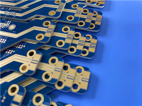
Manufactured fully compliant with IPC-6012 Class 3 aerospace/defense high-reliability criteria, the PCB targets integrated RF-digital modules including compact phased array antenna subassemblies, automotive 77GHz radar frontends, GPS receiver hardware, and portable microwave communication transceivers. Its fixed finished thickness of 1.014mm, mixed copper weight specification, advanced resin-plugged filled vias-in-pad architecture, and immersion gold surface finish deliver consistent impedance control, long-term thermal cycling resistance, and seamless component soldering. All dimensional tolerances, via plating integrity, material lamination bonding, and electrical performance undergo 100% automated AOI, flying probe electrical testing, and cross-section validation to meet zero-defect Class 3 acceptance thresholds.
2. PCB Construction Details
This table consolidates all mechanical, material, surface treatment and manufacturing standards of the finished hybrid PCB for engineering reference.
Table Summary: Complete mechanical, material, surface finish and production specification of the 4-layer RT6202+FR4 hybrid PCB
|
Parameter |
Specification |
|
Base Material |
RT/duroid 6202 + FR-4 |
|
Layer Count |
4 layers |
|
Board Dimensions |
110mm × 35mm (1 PCS) |
|
Finished Board Thickness |
1.014mm ±10% |
|
Finished Copper Weight (Outer Layers L1/L4) |
1 oz. (35 µm) |
|
Finished Copper Weight (Inner Layers L2/L3) |
0.5 oz. (18 µm) |
|
Via Plating Thickness |
25 µm minimum |
|
Hole Process |
Resin plug vias, electroplated filled vias, via-in-pad |
|
Surface Finish |
Immersion Gold (ENIG) |
|
Top Silkscreen |
White |
|
Bottom Silkscreen |
White |
|
Solder Mask (Top/Bottom) |
Blue |
|
Manufacturing Standard |
IPC-6012 Class 3 |
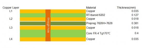
3. PCB Layer Stackup
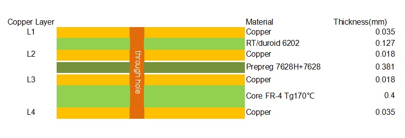
This table defines the symmetrical dielectric-copper layer sequence, clarifying material separation between high-frequency RT/duroid 6202 and cost-efficient FR-4 substrates.
Table Summary: Symmetrical 4-layer hybrid stackup layer sequence, dielectric thickness and material differentiation
4. Core Performance Advantages of Hybrid RT6202+FR4 Construction
4.1 High-Frequency Electrical Stability from RT/duroid 6202 Outer Layers
4.2 Cost & Density Optimization via FR-4 Inner Core
4.3 IPC-6012 Class 3 Reliability Features
5. PCB Conclusion
This 4-layer 5mil RT/duroid 6202 + FR-4 hybrid PCB represents a balanced high-reliability solution that bridges high-frequency microwave performance and economical digital circuit integration. By segregating RF signal layers on low-loss Rogers laminate and power/ground infrastructure on FR-4 core, the design eliminates the performance limitations of single-material PCBs while controlling material and production costs. Compliant with IPC-6012 Class 3 standards, equipped with advanced filled vias-in-pad architecture and stable immersion gold finishing, the board satisfies stringent electrical, mechanical and environmental requirements for radar, satellite communication, automotive millimeter-wave sensing, and high-precision antenna modules.
Its symmetrical stackup, tight dimensional control, and consistent impedance stability make it a scalable, production-ready hybrid platform for mixed RF-digital electronic systems, outperforming all-FR4 alternatives at multi-GHz frequencies and offering substantial cost savings versus fully Rogers multilayer PCBs.
Supplementary Complete CCL Knowledge: Rogers RT/duroid® 6202 High-Frequency Laminates
1. RT/duroid 6202 CCL Core Introduction
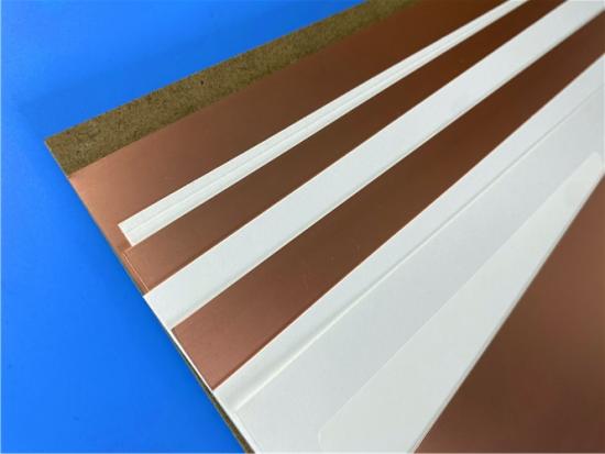
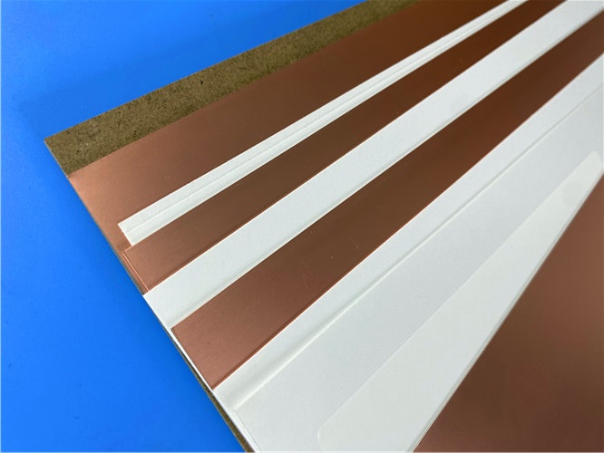
RT/duroid 6202 is a proprietary ceramic-filled PTFE-woven glass reinforced copper-clad laminate developed by Rogers Corporation, designed for complex microwave multilayer circuits, flat and conformal antenna structures, and hybrid RF-digital PCB stackups. The material formulation incorporates limited woven glass reinforcement to deliver industry-leading dimensional stability, eliminating secondary double etching operations for precision trace positioning. Unlike standard hydrocarbon or epoxy laminates, Rogers RT6202 maintains ultra-low dielectric loss and near-constant dielectric constant across wide temperature and frequency bands, with strict Dk tolerance controlled to±0.04 across all standard thickness grades. The laminate is fully compatible with lead-free high-temperature reflow processes and certified UL 94 V-0 flame retardant, making it suitable for commercial, industrial, aerospace and automotive high-frequency hardware.
Available dielectric thickness ranges from 0.005”(0.127mm, the grade deployed in thishybrid PCB) up to 0.060”(1.524mm), with standardized electrodeposited and rolled copper foil cladding weights from 0.5oz to 2oz/ft². Its primary differentiation from competing high-frequency CCLs lies in balanced electrical stability and mechanical manufacturability, supporting both single-sided circuits and complex hybrid multilayer stackups paired with FR-4, as implemented in the featured 4-layer PCB.
2. Full RT/duroid 6202 Datasheet Technical Parameter Table
Comprehensive electrical, mechanical, thermal and environmental property data of RT/duroid 6202 from official Rogers datasheet
|
Material Property |
Typical Test Value |
Test Direction |
Unit |
Test Condition |
Official Test Standard |
|
Dielectric Constant (εr), 5mil variant |
3.06 ± 0.04 |
Z Axis |
Dimensionless |
10GHz, 23°C |
IPC-TM-650, 2.5.5.5 |
|
Dissipation Factor (TAN δ) |
0.0015 |
Z Axis |
Dimensionless |
10GHz, 23°C |
IPC-TM-650, 2.5.5.5 |
|
Thermal Coefficient of εr |
5 |
Z Axis |
ppm/°C |
10GHz, -50 ~ +150°C |
IPC-TM-650, 2.5.5.5 |
|
Volume Resistivity |
10⁶ |
Z Axis |
Mohm·cm |
Ambient A Condition |
ASTM D257 |
|
Surface Resistivity |
10⁹ |
Z Axis |
Mohm |
Ambient A Condition |
ASTM D257 |
|
Tensile Modulus |
1007 (146) |
X, Y Plane |
MPa (kpsi) |
23°C |
ASTM D638 |
|
Ultimate Tensile Stress |
30 (4.3) |
X, Y Plane |
MPa (kpsi) |
23°C |
ASTM D638 |
|
Ultimate Tensile Strain |
4.9 |
X, Y Plane |
% |
23°C |
ASTM D638 |
|
Compressive Modulus |
1035 (150) |
Z Axis |
MPa (kpsi) |
23°C |
ASTM D638 |
|
Moisture Absorption |
0.04 |
Bulk |
% |
D23/24, D48/50 |
IPC-TM-650 2.6.2.1, ASTM D570 |
|
Thermal Conductivity |
0.68 |
Bulk |
W/m/K |
80°C |
ASTM C518 |
|
Coefficient of Thermal Expansion (CTE) |
15 |
X |
ppm/°C |
-55 ~ 288°C, 23°C/50% RH |
IPC-TM-650 2.4.41 |
|
15 |
Y |
||||
|
30 |
Z |
||||
|
Post-Etch Dimensional Stability |
0.07 |
X, Y Plane |
mil/inch |
Post Etch +E / 150°C Bake |
IPC-TM-650, 2.4.3.9 |
|
Thermal Decomposition Temperature (Td) |
500 |
Bulk |
°C |
TGA Thermal Scan |
ASTM D3850 |
|
Material Density |
2.1 |
Bulk |
g/cm³ |
Ambient Temperature |
ASTM D792 |
|
Specific Heat Capacity |
0.93 (0.22) |
Bulk |
J/g/K (BTU/lb/°F) |
Standard Ambient |
Calculated Industry Standard |
|
Copper Peel Strength |
9.1 (1.6) |
Cladding Interface |
lbs/in (N/mm) |
Standard Copper Foil |
IPC-TM-650 2.4.8 |
|
Flammability Rating |
V-0 |
N/A |
N/A |
N/A |
UL 94 |
|
Lead-Free Process Compatibility |
YES |
N/A |
N/A |
N/A |
N/A |
3. Standard Product Formats & Thickness Grades of RT/duroid 6202 CCL
3.1 Standard Dielectric Thickness Specs
Non-standard custom thicknesses are available ranging from 0.005”to 0.060”upon customer engineering request.
3.2 Standard Panel Dimensions
Custom oversized panels can be ordered via Rogers sales engineering department.
3.3 Standard Copper Cladding Options
Additional specialty claddings including resistive foil and reverse-treated ED copper are configurable for specialized RF circuit designs.
4. Some Typical Applications for RT/duroid 6202
• Phased Array Antennas
• Ground Based and Airborne Radar Systems
• Global Positioning System Antennas
• Power Backplanes
• High Reliability Complex Multilayer Circuits
• Commercial Airline Collision Avoidance Systems
• Beam Forming Networks
5. RT/duroid 6202 CCL Conclusion
Rogers RT/duroid 6202 copper-clad laminate delivers a unique combination of ultra-low high-frequency loss, tightly controlled dielectric constant, exceptional dimensional stability, and robust mechanical performance that cannot be replicated by conventional FR-4 substrates at microwave frequencies. Its graded Dk values tailored to different dielectric thicknesses, wide thermal operating window, lead-free reflow compatibility, and UL V-0 flame retardancy establish it as a foundational CCL material for hybrid RF-digital multilayer PCBs such as the 4-layer 5mil RT6202+FR4 board detailed above.
When deployed selectively on only critical RF outer layers paired with cost-effective FR-4 inner cores, RT/duroid 6202 substrate balances premium high-frequency electrical performance with controlled production expenditure, forming the optimal substrate solution for Class 3 high-reliability radar, antenna, and wireless communication electronic hardware.





Previous:
6-Layer 10mil RO4350B + IT180A Hybrid PCB with ENIG Blind Via Edge PlatingNext:
12-Layer RO4350B + RO3010 3.14mm Hybrid PCB Nickel-Free EPIG Surface Finish Blind ViaIf you have questions or suggestions,please leave us a message,we will reply you as soon as we can!
Categories
New Products

Wangling F4BTMS220 2-Layer DK2.2 PCB 10 mil Core with Immersion Gold

Wangling F4BTME350 10mil DK3.5 High Frequency Substrate PCB 2-Layer Immersion Gold

Wangling F4BTM300 Custom 2-layer PCB 20mil DK3.0 Substrate with Immersion Gold

Rogers 20mil RT/duroid 6202 2-layer ENIG High-Frequency Microwave PCB

Rogers 20mil AD250C PCB Pure Gold High-Frequency Antenna Circuit Board

8-Layer Hybrid RF PCB: RO4350B + TG170 FR-4 + RO4003C with RO4450F Bondply

4-Layer Rogers RO3010 Hybrid PCB Immersion Silver 2.8mm Finished Thickness

4-Layer 20mil Rogers RO3210 ISIG High-Frequency PCB with Controlled Depth Milling
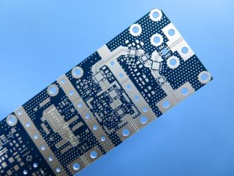
RO4003C exhibit a stable dielectric constant over a broad frequency range. This makes it an ideal substrate for broadband applications. And signal integrity performance improvement over the stack-ups with all FR4 board.
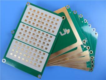
The hybrid PCB can be a mixture of FR-4 and high frequency material, and a mixture of high frequency material with different dielectric constant (DK)
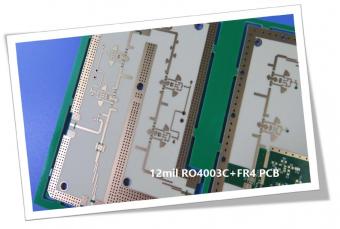
The 12mil core is on the top layer and it mainly plays the roles of signal layer. The core has fixed thickness which is very important to the electrical length of RF lines on the circuit board.
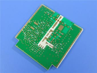
The hybrid PCB can be a mixture of FR-4 and high frequency material as abovementioned.
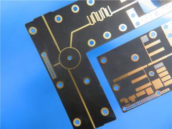
It contains 2 different boards in the panel. PCB boards are manufactured strictly as per required specifications with the standard IPC-Class-II.
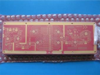
Hybrid PCB is also known as mixed material lamination, it’s normally combined by two different material like FR4 and PI(rigid flex PCB), FR4 and Ceramic, FR4 and Teflon, FR4 and Aluminum base etc.
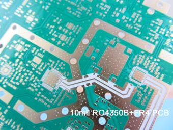
Hybrid constructions PCB typically involve a low loss material such as Nelco or Rogers combined with another core material like FR-4.
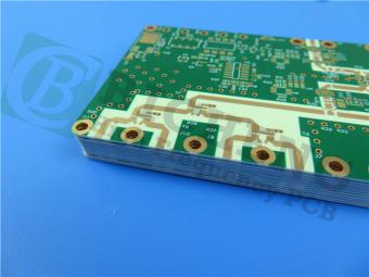
The Hybrid PCB on RO3003 and High Tg FR-4 is a state-of-the-art solution for high-frequency applications. With its exceptional stability, reliability, and manufacturability, it caters to the demands of industries such as automotive, telecommunications, and satellite communications.
 6-11C Shidai Jingyuan, Fuyong, Baoan, Shenzhen, Guangdong, China 518103


For inquiries about our products or pricelist, please leave to us and we will be in touch within 24 hours.
© Copyright: 2026 Shenzhen Bicheng Electronics Technology Co., Ltd.. All Rights Reserved.

IPv6 network supported


