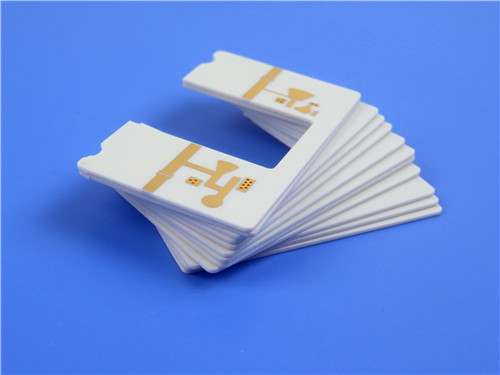
Why Dk/Df Values Matter: Dielectric Properties' Impact on Signal Integrity in High-Frequency PCBs
Introduction
In the world of high-frequency printed circuit boards(PCBs), signal integrity is paramount. As data rates increase and wireless technologies evolve, the dielectric properties of PCB materials play a critical role in ensuring reliable performance. Two key parameters—dielectric constant (Dk) and dissipation factor (Df)—directly influence signal propagation, impedance control, and power loss.
For engineers and designers selecting PCB materials, understanding Dk and Df is essential to optimizing performance in RF, microwave, and high-speed digital applications. This article explores why these values matter, how they affect signal integrity, and why Rogers RO4003C—a high-performance laminate—is an excellent choice for demanding applications.
Understanding Dk and Df: The Basics
1. Dielectric Constant (Dk)–The Speed of Signals
The dielectric constant (Dk), also called relative permittivity (εᵣ), measures how much a material slows down an electromagnetic wave compared to a vacuum (where Dk = 1).
-
Higher Dk→Signals travel slower, wavelengths shorten, and trace dimensions must be adjusted to maintain impedance.
-
Lower Dk→Signals propagate faster, allowing for better high-frequency performance.
For example, Rogers RO4003C PCB has a Dk of 3.38±0.05 at 10 GHz, offering a stable and predictable electrical response—crucial for RF and microwave designs.
2. Dissipation Factor (Df)–The Loss Mechanism
The dissipation factor (Df), or loss tangent, quantifies a material’s inherent signal loss due to dielectric absorption.
-
Higher Df→More energy is lost as heat, degrading signal strength (critical in high-frequency applications).
-
Lower Df→Less loss, better signal integrity, and improved efficiency.
RO4003C boasts an ultra-low Df of 0.0027 at 10 GHz, making it ideal for high-frequency circuits where minimal loss is required.

Why Dk/Df Values Are Critical for Signal Integrity
1. Impedance Control & Signal Reflections
Impedance mismatches cause signal reflections, leading to distortions and data errors. Since trace impedance depends on Dk, a stable dielectric constant ensures consistent performance.
-
RO4003C’s tight Dk tolerance (±0.05) allows precise impedance matching, reducing reflections.
-
Its low Df minimizes insertion loss, preserving signal strength over long traces.
2. Insertion Loss & High-Frequency Performance
At microwave frequencies (e.g., 5G, radar, satellite comms), even minor losses can degrade system performance.
-
RO4003C’s low-loss properties (Df = 0.0027 at 10 GHz) ensure minimal attenuation.
-
Compared to FR4 (Df ~0.02), RO4003C offers 10x lower loss, making it superior for RF applications.
3. Thermal Stability & Reliability
Temperature fluctuations can shift Dk, altering circuit behavior. RO4003C’s thermal coefficient of Dk (+40 ppm/°C) ensures stability across operating conditions.
Additionally, its low Z-axis CTE (46 ppm/°C) prevents via cracking under thermal stress—critical for high-reliability applications like automotive radar.
RO4003C: A High-Performance PCB Material for Demanding Applications
Key Features of RO4003C
-
Dk = 3.38±0.05 @ 10 GHz (consistent across frequency bands)
-
Df = 0.0027 @ 10 GHz (ultra-low loss for RF/microwave)
-
Thermal Conductivity = 0.71 W/m/°K (better heat dissipation than FR4)
-
Low Moisture Absorption (0.06%) (prevents performance drift in humid environments)
-
Compatible with Standard FR4 Processes (reduces fabrication costs)
Why Choose RO4003C Over FR4?
|
Parameter
|
RO4003C
|
Standard FR4
|
Advantage
|
|
Dk Stability
|
3.38 ±0.05
|
~4.3 (varies with frequency)
|
Better impedance control
|
|
Dissipation Factor
|
0.0027 @ 10 GHz
|
~0.02
|
Lower insertion loss
|
|
Thermal Conductivity
|
0.71 W/m/°K
|
~0.3 W/m/°K
|
Improved heat dissipation
|
|
CTE (Z-axis)
|
46 ppm/°C
|
~70 ppm/°C
|
More reliable plated through-holes
|
Typical Applications
-
5G & Cellular Base Stations (low loss for power amplifiers & antennas)
-
Automotive Radar (77 GHz ADAS systems) (stable Dk for mmWave frequencies)
-
RFID & Satellite Communications (minimal signal degradation)
-
High-Speed Digital PCBs (reduced crosstalk & EMI)
Our PCB Manufacturing Capabilities with RO4003C
We specialize in high-frequency PCB susing Rogers 4003C, ensuring optimal signal integrity for your designs.
PCB Specifications:
Layers: 2-layer rigid
Base Material: Rogers RO4003C (1.524 mm core)
Copper Weight: 1 oz (35μm)
Minimum Trace/Space: 6/10 mils
Surface Finish: ENIG (Electroless Nickel Immersion Gold)
Quality Standard: IPC-Class-2
100% Electrical Testing before shipment
Why Partner with Us?
✔Global Availability–Reliable shipping worldwide
✔Cost-Effective Processing–No special handling required (unlike PTFE)
✔High-Frequency Expertise–Optimized for RF/microwave applications
Conclusion: The Right Material Makes the Difference
In high-frequency PCB design, Dk and Df values are not just specifications—they define performance. Rogers RO4003C’s low-loss, stable Dk, and thermal reliability make it an outstanding choice for 5G, automotive radar, and RF applications.
By selecting a PCB supplier with expertise inhigh-frequency materials, you ensure optimal signal integrity, reduced losses, and long-term reliability.
Need a high-performance RO4003C PCB? Contact us today for a quote!

 Call Us Now !
Tel : +86 755 27374946
 Order Online Now !
Email : info@bichengpcb.com


