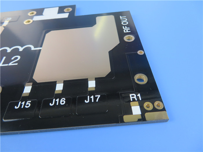
RF and Microwave PCB
In comparison to ordinary boards, radio frequency (RF) boards are built to function at frequencies higher than 100 MHz. The PCB industry has been forced to improve its ability to add more circuits to the boards and handle greater frequency ranges by the expanding IOT market.

In the PCB sector, we constantly adapt to new trends and technology. We have improved our capabilities and created a unique process and production line to carefully produce high-quality RF and microwave boards.
High frequency circuit board production is a specialty of our engineering and production teams. For comprehensive design solutions, we carefully collaborate with customers to choose the right
PCB materials.
You should take into account important elements while designing your RF boards, such as noise reduction, impedance matching, return loss reduction, and cross talk reduction by choosing suitable laminates (dissipation factor and dielectric constant for a low loss board).
The most crucial element in achieving a cost-performance balance is the choice of the appropriate materials. To develop RF boards, materials such as polytetrafluoroethylene (PTFE), ceramics, hydrocarbon, and a variety of class materials—including hybrid stack-ups—are used.
To meet the needs of the customer and go above and beyond their expectations, our in-house RF and Microwave experts make sure that factors/requirements like coefficient of thermal expansion (CTE), dielectric constant, thermal coefficient, relative permittivity, and loss tangent are taken into account at the preliminary stages.
LAMINATE CONDITIONS
An RF or microwave PCB's functionality may be significantly impacted by the characteristics of a PCB laminate. For instance, FR4 laminates may experience increased insertion losses as signal frequencies rise because FR4 laminates have a higher dissipation factor than high-frequency laminates. In addition, FR4 often has a greater and more variable dielectric constant, or Dk value, than high frequency laminates. The impedance can change as a result of variations in FR4 Dk values of up to 10%.
Dielectric loss is a frequent issue related to the laminate's characteristics. Dielectric loss happens when electrons pass through a conductor and bounce off the electrons of the
FR4 PCB substrate, much like skin effect loss does. Some of the signal energy from the flowing electrons is passed to the FR4 electrons during their interaction, and the FR4 electrons then transform the energy into heat. Utilizing substrates with extremely low dissipation factors, such as polytetrafluoroethylene Teflon, which has a dissipation factor of roughly 0.001 as opposed to FR4's dissipation factor of 0.02 can prevent this kind of loss.

 Call Us Now !
Tel : +86 755 27374946
 Order Online Now !
Email : info@bichengpcb.com


