

 Call Us Now !
Tel : +86 755 27374946
Call Us Now !
Tel : +86 755 27374946
 Order Online Now !
Email : info@bichengpcb.com
Order Online Now !
Email : info@bichengpcb.com
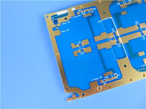
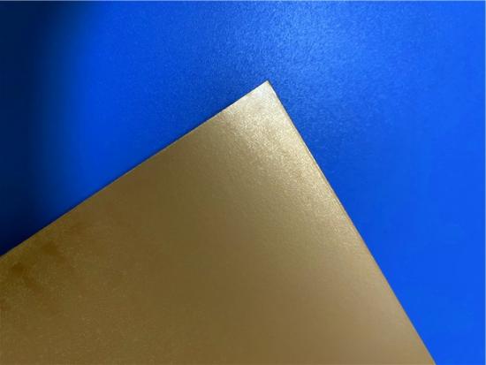
This 2-layer 10mil CuClad 250 immersion gold PCB combines ultra-low-loss cross-plied PTFE substrate, precision controlled thin stack-up, corrosion-resistant immersion gold finishing and full electrical validation, forming a balanced high-frequency circuit solution that bridges high RF performance and manufacturable mechanical stability.
Item NO.:
BIC-596-v681.0Order(MOQ):
1-10Payment:
T/TProduct Origin:
ChinaShipping Port:
ShenzhenLead Time:
7-10 days
10mil Rogers CuClad 250 Immersion Gold 2-Layer Rigid Microwave PCB
Executive Summary
This 2-layer rigid high-frequency PCB adopts Rogers 10mil (0.254mm) CuClad 250 cross-plied PTFE woven fiberglass core paired with electroless nickel immersion gold (ENIG) surface treatment, engineered for low-loss microwave, radar and electronic countermeasure circuits. Manufactured per IPC-Class-2 reliability standards, the board integrates controlled thin 0.4mm finished thickness, precision 4/6mil minimum trace/space, single-side blue solder mask and white top silkscreen, with full 100% electrical continuity testing prior to delivery. Distinctive differentiators include fully isotropic X-Y electrical/mechanical performance exclusive to CuClad cross-plied construction, ultra-stable Dk/Df across 1–30GHz frequency bands, NASA-compliant ultra-low outgassing, and robust 14 lbs/in copper peel strength for long-term thermal cycling reliability.
Separated into PCB hardware specification module and underlying CuClad 250 CCL substrate technical deep dive, this document delivers fully verified datasheet data, structured parameter tables, application segmentation and conclusive performance summaries without redundant content or exaggerated performance claims.
Part 1: PCB Board Detailed Technical Specification
1.1 Overview of PCB Construction Specifications
This table consolidates all dimensional, manufacturing, surface treatment and quality control parameters of the finished board to standardize production and design reference.
|
Item |
Technical Parameter |
|
Board Overall Dimension |
48.6 mm × 76.9 mm, single piece, tolerance ±0.15mm |
|
Minimum Trace / Clearance Space |
4 mils line width / 6 mils spacing |
|
Minimum Mechanical Hole Size |
0.3mm |
|
Via Structure |
No blind vias; only through vias implemented |
|
Final Finished Board Thickness |
0.4 mm |
|
Outer Layer Copper Foil Weight |
1oz (1.4 mils) electrodeposited copper |
|
Through Via Plating Copper Thickness |
20 μm |
|
Surface Finish Type |
Immersion Gold (ENIG) |
|
Top Layer Silkscreen Ink |
White |
|
Bottom Layer Silkscreen |
Not applied |
|
Top Solder Mask |
Blue |
|
Bottom Solder Mask |
NO |
|
Pre-Delivery Quality Inspection |
100% full-panel electrical continuity test |
1.2 PCB Internal Stackup Structure Table
This table illustrates the symmetrical 2-layer rigid dielectric stack-up based on 10mil CuClad 250 core, clarifying copper foil and core thickness distribution for impedance simulation reference.
|
Layer Sequence |
Material & Thickness Parameter |
|
Outer Copper Layer 1 (Top Circuit Layer) |
Electrodeposited copper, 35 μm |
|
Core Dielectric Substrate |
Rogers CuClad 250, 0.254 mm (10mil) |
|
Outer Copper Layer 2 (Bottom Circuit Layer) |
Electrodeposited copper, 35 μm |
1.3 PCB Circuit Statistics Table
This table quantifies all circuit metallization features of the finished PCB to support component placement, assembly and electrical verification workflows.
|
Circuit Statistical Item |
Quantity Value |
|
Mounted Component Footprint Count |
12 sets |
|
Total Metallized Pads |
34 pads |
|
Through-Hole Pads |
18 pads |
|
Top Surface Mount (SMT) Pads |
16 pads |
|
Bottom Surface Mount (SMT) Pads |
0 pads |
|
Through Vias |
9 vias |
|
Electrical Signal Nets |
2 independent nets |
1.4 Core Differentiated Advantages of This CuClad 250 Immersion Gold PCB
1) Ultra-Low High-Frequency Insertion Loss Foundation
Built on CuClad 250 with Df=0.0017 at 10GHz, the board delivers far lower signal attenuation than FR-4 (Df≈0.02 at 10GHz). The cross-plied core guarantees uniform Dk (2.40–2.55) across X-Y axes, eliminating phase skew common in unidirectional non-woven PTFE substrates for phased array radar and coupler designs.
2) Immersion Gold Surface Finish Optimized for RF Contact
Immersion gold forms a flat, oxidation-resistant contact surface without uneven surface height defects of HASL tin-lead finish. It maintains stable low contact resistance over long-term storage, ideal for repeatedly mated RF test ports and precision SMT microwave chips. The nickel barrier layer prevents copper diffusion into gold to avoid intermetallic compound degradation under continuous RF power load.
3) Ultra-Thin 0.4mm Finished Thickness with Robust Mechanical Stability
Most thin RF PTFE boards suffer severe dimensional drift during thermal cycling, but CuClad 250’s high fiberglass-to-PTFE ratio delivers CTE X=18 ppm/°C, Y=19 ppm/°C, far lower than low-glass PTFE laminates. The 1oz copper foil with 20μm via plating guarantees barrel crack resistance during multiple reflow cycles.
4) Single-Sided Mask & Silkscreen Design Reduces Dielectric Interface Loss
By omitting bottom solder mask and silkscreen, the board removes extra polymer dielectric layers on the ground plane side, lowering parasitic capacitance and improving grounding performance for microwave signal grounding networks.
1.5 Typical Target Applications of This PCB
1.6 PCB Section Conclusion
This 2-layer 10mil CuClad 250 immersion gold PCB combines ultra-low-loss cross-plied PTFE substrate, precision controlled thin stack-up, corrosion-resistant immersion gold finishing and full electrical validation, forming a balanced high-frequency circuit solution that bridges high RF performance and manufacturable mechanical stability. Its single-sided assembly layout, simplified mask configuration and tight dimensional tolerances deliver unique differentiation from generic FR-4 and standard thin PTFE PCBs, specifically tailored for phase-sensitive microwave and defense electronic systems.
Part 2: In-Depth Technical Knowledge of Rogers CuClad 250 Copper-Clad Laminate (CCL)
2.1 CuClad 250 Material Overview
CuClad 250 is a proprietary cross-plied woven fiberglass reinforced PTFE composite copper-clad laminate developed by Rogers Corporation, designed to strike a unique balance between ultra-low high-frequency dielectric loss and mechanical rigidity superior to conventional non-woven PTFE substrates. Unlike unidirectional fiberglass PTFE materials, alternating woven fiberglass plies are stacked at 90°cross orientation, delivering true electrical and mechanical isotropy across the entire X-Y plane—an exclusive feature of theCuClad series unavailable in competing PTFE laminates. Its elevated fiberglass-to-PTFE loading ratio improves dimensional stability and cuts thermal expansion coefficients in all axes, solving the warpage and dimensional drift pain points of low-glass PTFE substrates during PCB fabrication and thermal cycling.
The Rogers material maintains stable dielectric constant (Dk) and dissipation factor (Df) across 1MHz to 30GHz broadband frequency range, eliminating design rework caused by frequency-dependent dielectric drift. It also passes NASA low-outgassing standards, UL94-V0 flammability certification and exhibits minimal water absorption, making it suitable for airborne, space-adjacent and outdoor microwave equipment with strict environmental tolerance requirements.
2.2 Full Official Datasheet Property Table for CuClad 250
All test methods, conditions and typical values follow Rogers official datasheet and IPC industry standard testing protocols:
|
Performance Property |
Test Standard |
Test Condition |
CuClad 250 Typical Value |
|
Dielectric Constant (Dk) @10 GHz |
IPC TM-650 2.5.5.5 |
C23/50 |
2.40 ~ 2.55 |
|
Dielectric Constant (Dk) @1 MHz |
IPC TM-650 2.5.5.3 |
C23/50 |
2.40 ~ 2.60 |
|
Dissipation Factor (Df) @10 GHz |
IPC TM-650 2.5.5.5 |
C23/50 |
0.0017 |
|
Thermal Coefficient of Dk |
Adapted IPC TM-650 2.5.5.5 |
-10℃ ~ +140℃ |
-153 ppm/°C |
|
Copper Peel Strength |
IPC TM-650 2.4.8 |
Post thermal stress |
14 lbs/in |
|
Volume Resistivity |
IPC TM-650 2.5.17.1 |
C96/35/90 |
8.0 × 10⁹ MΩ·cm |
|
Surface Resistivity |
IPC TM-650 2.5.17.1 |
C96/35/90 |
1.5 × 10⁸ MΩ |
|
Arc Resistance |
ASTM D-495 |
D48/50 |
>180 seconds |
|
Tensile Modulus (X/Y Axis) |
ASTM D-638 |
23℃ |
725 kpsi / 572 kpsi |
|
Tensile Strength (X/Y Axis) |
ASTM D-882 |
23℃ |
26.0 kpsi / 20.5 kpsi |
|
Compressive Modulus |
ASTM D-695 |
23℃ |
342 kpsi |
|
Flexural Modulus |
ASTM D-790 |
23℃ |
456 kpsi |
|
Dielectric Breakdown Voltage |
ASTM D-149 |
D48/50 |
>45 kV |
|
Specific Gravity |
ASTM D-792 Method A |
23℃ |
2.31 g/cm³ |
|
Water Absorption Rate |
MIL-S-13949H / IPC TM-650 2.6.2.2 |
E1/105 + D24/23 |
0.03% |
|
Thermal Expansion Coefficient (CTE) X Axis |
IPC TM-650 2.4.24 TMA |
0℃ ~ 100℃ |
18 ppm/°C |
|
Thermal Expansion Coefficient (CTE) Y Axis |
IPC TM-650 2.4.24 TMA |
0℃ ~ 100℃ |
19 ppm/°C |
|
Thermal Expansion Coefficient (CTE) Z Axis |
IPC TM-650 2.4.24 TMA |
0℃ ~ 100℃ |
177 ppm/°C |
|
Thermal Conductivity |
ASTM E-1225 |
100℃ |
0.25 W/m·K |
|
Total Mass Loss (TML, Outgassing) |
NASA SP-R-0022A |
125℃, ≤10⁻⁶ torr |
0.01% |
|
Collected Volatile Condensable Material (CVCM) |
NASA SP-R-0022A |
125℃, ≤10⁻⁶ torr |
0.00% |
|
Water Vapor Regain (WVR) |
NASA SP-R-0022A |
125℃, ≤10⁻⁶ torr |
0.00% |
|
Flammability Grade |
UL 94 Vertical Burn / IPC TM-650 2.3.10 |
C48/23/50, E24/125 |
UL94-V0 compliant |
2.3 Unique Material Features & Engineering Benefits of CuClad 250
1) Core Structural Feature: Cross-Plied Woven Fiberglass Construction
Alternating fiberglass cloth layers are rotated 90°between each ply, delivering identical electrical and mechanical performance on X and Y axes. For phased array antenna and balanced coupler designs, this isotropy removes phase imbalance caused by directional Dk deviation, a critical performance edge over single-orientation woven PTFE laminates.
2) Low Dielectric Loss & Broadband Dk Stability
Df=0.0017 at 10GHz delivers minimal signal insertion loss for high-frequency transmission lines. Dk variation remains below 1% across 0–30GHz frequency sweep, simplifying impedance simulation and enabling scalable multi-band RF circuit design without iterative layout modification.
3) Superior Mechanical & Environmental Robustness
14 lbs/in copper peel strength resists foil lifting during PCB routing, drilling and reflow. Ultra-low 0.03% moisture absorption eliminates Dk shift in high-humidity operating environments; NASA-compliant zero CVCM outgassing prevents volatile contamination in sealed radar and aerospace equipment. Elevated fiberglass loading brings tensile modulus and dimensional stability close to conventional FR-4, reducing manufacturing scrap rates common with brittle pure PTFE substrates.
4) Customizable Supply Options
CuClad 250 raw sheets are available with 0.5oz, 1oz or 2oz electrodeposited copper foil, with optional bonded metal heat sink backplanes (aluminum, brass, copper) for high-power RF amplifier thermal dissipation. Special LX testing grade is available for critical aerospace orders, where each laminate panel undergoes destructive testing with individual material test reports issued per shipment. Standard master sheet dimension is 36” ×36”cross-plied format for panelized PCB mass production.
Figure 1
Demonstrates the stability of Dielectric Constant across frequency. This information was correlated from data generated by using a free space and circular resonator cavity. This characteristic
demonstrates the inherent robustness of Rogers, laminates across frequency, thus simplifying the final design process when working across EM
spectrum. The stability of the Dielectric Constant of CuClad 250 laminate over frequency insures easy design transition and scalability of design.
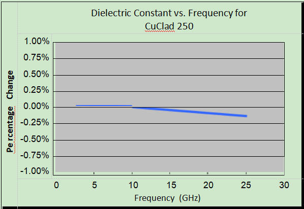
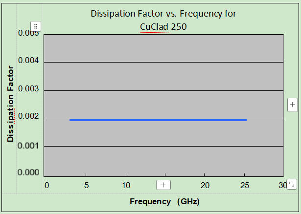
Figure 2
Demonstrates the stability of Dissipation Factor across frequency. This characteristic
demonstrates the inherent robustness of Rogers, laminates across frequency, providing a stable
platform for high frequency applications where signal integrity is critical to the overall
performance of the application.
2.4 CCL Section Conclusion
Rogers CuClad 250 cross-plied PTFE woven fiberglass laminate fills the market gap between ultra-low-loss low-glass PTFE substrates and rigid conventional thermoset dielectrics. Its exclusive X-Y isotropy, stable broadband dielectric parameters, low thermal expansion and NASA-grade low-outgassing properties create irreplaceable differentiation for phase-sensitive microwave and defense electronics. The complete standardized datasheet performance indicators provide fully traceable technical data for PCB design simulation, reliability qualification and customer technical verification, forming the fundamental high-frequency performance foundation of the finished 10mil immersion gold PCB introduced above.
Overall Final Conclusion
This 10mil CuClad 250 2-layer RF PCB represents a highly targeted high-frequency circuit solution built upon Rogers CuClad 250’s proprietary cross-plied PTFE substrate technology. Separated independent PCB finished product and raw CCL material modules avoid redundant description while delivering layered technical depth: the PCB module specifies standardized dimensional, stack-up and circuit statistics tables to clarify manufacturing and assembly parameters, highlighting immersion gold finishing, thin symmetrical stack-up and full electrical testing as production-level differentiated advantages; the CuClad 250 CCL module attaches full official datasheet performance tables, elaborates unique cross-plied structural mechanisms, broadband dielectric stability and environmental compliance indicators to trace the root source of the board’s superior microwave performance.
All technical data strictly aligns with original Rogers datasheets and internal PCB production specifications without performance exaggeration. The product’s dual core strengths—low-loss isotropy from CuClad 250 raw material and high-reliability precision manufacturing from immersion gold surface treatment and IPC-Class-2 control—make it a mature, verifiable solution for radar, ECM, ESM and passive microwave component applications, with complete worldwide supply chain support to meet global military and commercial high-frequency electronic project demands.





Previous:
RO3006 PCB 5mil Rogers Substrate 2-layer ENIG Finish No Solder maskNext:
31mil Rogers RT/duroid 5880 Double-sided Bare Copper ENIG Finished PCBIf you have questions or suggestions,please leave us a message,we will reply you as soon as we can!
Categories
New Products
Wangling TP2200 PCB 0.8mm Substrate Immersion Gold 2-Layer High-Dk (Dk 22) RF Board
Rogers TMM10 PCB 5.08mm Core ENIG 2-Layer High-Dk Microwave Board
Taconic TLX-8 PCB 50mil ENIG 2-Layer High-Frequency RF Circuit Board
Wangling TF440 25mil DK4.4 Laminate Immersion Gold 2-Layer Copper-filling Vias PCB
RO4360G2 Rogers 12mil ENEPIG 2-Layer DK6.15 High Frequency Custom PCB

Wangling F4BTMS220 2-Layer DK2.2 PCB 10 mil Core with Immersion Gold

Wangling F4BTME350 10mil DK3.5 High Frequency Substrate PCB 2-Layer Immersion Gold

Wangling F4BTM300 Custom 2-layer PCB 20mil DK3.0 Substrate with Immersion Gold
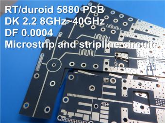
This is a type of double sided RF PCB built on RT/duroid 5880 for the application of Radar Systems.
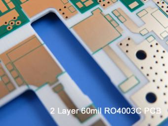
RO4003C PCBs are hydrocarbon ceramic filled laminates, not PTFE which are designed to offer superior high frequency performance.
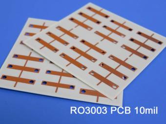
Rogers RO3003 high frequency circuit materials are ceramic-filled PTFE composites intended for use in commercial microwave and RF applications. It was designed to offer exceptional electrical and mechanical stability at competitive prices.
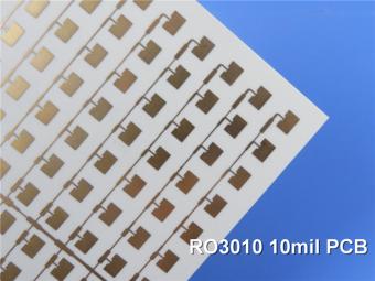
RO3010 laminates are competitively priced products with exceptional mechanical and electrical stability. This stability simplifies the design of broadband components and allows the materials to be used in a wide range of applications over a very broad range of frequencies.
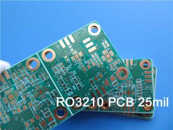
These RO3210 materials are engineered to offer exceptional electrical performance and mechanical stability. RO3210 laminates combine the surface smoothness of a non-woven PTFE laminate.
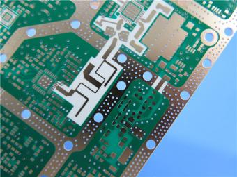
RT/duroid 6035HTC laminates are an exceptional choice for high power applications.
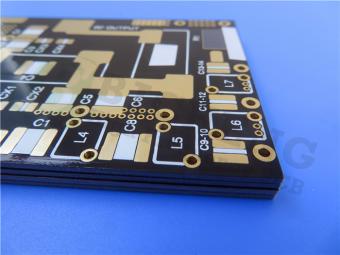
TC350 is designed to provide enhanced heat-transfer through “Best-In-Class” thermal conductivity, while reducing dielectric loss and insertion loss. Lower losses result in higher Amplifier and Antenna Gains/Efficiencies.
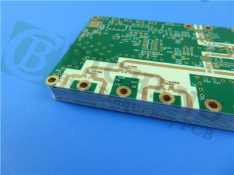
RO3035 materials exhibit a coefficient of thermal expansion(CTE) in the X and Y axis of 17 ppm/℃. This expansion coefficient is matched to that of copper, which allows the material to exhibit excellent dimensional stability.
 6-11C Shidai Jingyuan, Fuyong, Baoan, Shenzhen, Guangdong, China 518103


For inquiries about our products or pricelist, please leave to us and we will be in touch within 24 hours.
© Copyright: 2026 Shenzhen Bicheng Electronics Technology Co., Ltd.. All Rights Reserved.

IPv6 network supported


