
 Call Us Now !
Tel : +86 755 27374946
Call Us Now !
Tel : +86 755 27374946
 Order Online Now !
Email : info@bichengpcb.com
Order Online Now !
Email : info@bichengpcb.com
Enhancing Industry Independence with Cutting-Edge PCB Technology Focusing on high-end and automation PCBs (printed circuit boards) are to the electronics industry what steel is to real estate and asphalt is to roads and bridges. At the beginning of the 21st century, the dawn of China's electronics industry sounded in Shenzhen. Japanese, Korean, and Taiwanese companies expanded their territories in South China, pressing the accelerator for China's electronic manufacturing industry. At that time, the most fundamental part of the industry chain and the demand for massive PCBs made it the first entry point for Chinese electronic industry practitioners to start their own businesses. Focusing on high-end PCBs and serving display panel companies became the path to success for Li Xiaohua in their uninterrupted 20-year entrepreneurial journey. Targeting the high-end market "Printed circuit boards are the most fundamental components of the electronic manufacturing industry, known as the 'mother of electronic products.' Mobile phones, tablets, and other electronic consumer goods, as well as various other industries such as artificial satellites, spacecraft, airplanes, ships, and even the current new energy vehicles, cannot do without the application of electronic products. Circuit boards are the carriers for all electronic product applications. Therefore, when we chose to enter this industry, we believed that it had broad future applications and significant development potential," explained Li Xiaohua, Chairman. At the beginning of the 21st century, lightweight electronic products such as smart wearable devices began to gain popularity, and the demand for PCBs shifted towards lighter and more flexible directions. At that time, multi-touch screens represented by the Nintendo NDS game console became a global sensation. In 2004, Apple internally initiated the "Purple2" project, shifting the company's focus from iPods and iPads to large-screen touch smartphones. The "Purple2" project eventually led to the creation of the iPhone series. Manufacturing smartphones is like "building a dojo inside a snail's shell," and circuit boards, as basic electronic components, also started to require lightweight, flexible designs while overcoming various extreme conditions. Li Xiaohua noticed this trend and ultimately decided to focus on Flexible Printed Circuit (FPC) as PCB supplier' entrepreneurial direction. "Flexible circuit boards are used in scenarios like phone screens, laptop screens, and tablet screens. So, at that time, we conducted a detailed market analysis and ultimately determined to serve the entire display panel industry," said Li Xiaohua. Entering the Chip-on-Film (COF) industry marked the beginning ofPCB supplier' foray into the high-end market. "Starting in 2016, FPC began to develop towards lighter, thinner, and finer lines. The flexible narrow board for driving display panels became representative of these fine lin...

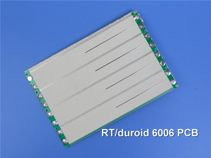
RT/duroid 6006 PCB 25mil: A Game-Changer in the High-Frequency PCB Industry Introduction The high-frequency PCB industry is witnessing a significant breakthrough with the introduction of the RT/duroid 6006 PCB 25mil. This advanced technology promises to revolutionize high-frequency applications by providing unprecedented performance and reliability. This article delves into the details of this groundbreaking development and explores its potential implications for the industry. Unveiling the RT/duroid 6006 PCB 25mil RT/duroid 6006 PCB 25mil is a cutting-edge high-frequency material designed to meet the stringent demands of modern electronic devices and communication systems. Leveraging state-of-the-art technology, this PCB substrate offers exceptional electrical performance, mechanical stability, and thermal resilience. Its ultra-low loss tangent and high-reliability characteristics enable engineers to design and manufacture high-frequency circuits that deliver unparalleled signal integrity and performance. Unmatched Electrical Performance The key advantage of Rogers 6006 high frequency PCB 25mil lies in its outstanding electrical properties. With an extremely low dielectric constant (εr) of 6.15±0.15, it enables the precise propagation of high-frequency signals with minimal distortion. This low εr ensures controlled impedance, reduces signal loss, and enhances the overall circuit performance. Moreover, the material's low dissipation factor (loss tangent) of 0.0025 ensures minimal energy loss, thus optimizing signal transmission efficiency. This feature is particularly crucial in high-frequency applications, such as radar systems, satellite communication, and advanced wireless networks, where accurate signal reproduction is vital. Mechanical Stability and Thermal Resilience Apart from superior electrical properties, the Rogers 6006 PCB exhibits remarkable mechanical stability and thermal resilience. Its glass-reinforced construction enhances its rigidity, making it resistant to warping or twisting, even in challenging operating conditions. This attribute reduces the risk of signal distortion due to mechanical stresses, ensuring reliable performance over an extended period. Furthermore, the material's low moisture absorption and excellent thermal conductivity enable effective heat dissipation. Heat management is crucial for maintaining circuit integrity and preventing performance degradation, especially in high-power applications. The RT/duroid 6006 PCB 25mil's ability to handle high temperatures and dissipate heat efficiently positions it as an optimal choice for high-frequency applications operating in demanding environments. Design Flexibility and Manufacturability In addition to its exceptional electrical and mechanical properties, the RT/duroid 6006 PCB 25mil substrate offers design flexibility and ease of manufacturing. Its compatibility with traditional fabrication processes allows P...
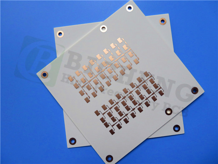
Introducing the RO4003C 60mil PCB: Revolutionizing High-Frequency Applications in the PCB Industry We are thrilled to unveil our newly shipped PCB, the RO4003C 60mil PCB, designed to address the latest industry trends and meet the growing demands of high-frequency applications. With its exceptional features and benefits, this cutting-edge substrate is set to revolutionize the PCB industry. In recent PCB industry news, there has been a significant focus on the need for higher operating frequencies and improved performance. As technology continues to advance rapidly, there is a growing demand for PCB solutions that can support these emerging requirements. Our RO4003C 60mil PCB is perfectly positioned to meet these needs, offering a range of features that ensure unparalleled performance and reliability. The RO4003C PCB is manufactured using Rogers' woven glass reinforced hydrocarbon/ceramics material, providing low dielectric tolerance and low loss. With a dielectric constant (DK) of 3.38 +/-0.05 at 10GHz and a dissipation factor of 0.0027 at 10GHz, this Rogers substrate guarantees excellent electrical performance. These properties allow for applications with higher operating frequencies, making it ideal for broadband applications. One of the key industry trends is the demand for stable electrical properties across a wide frequency range. Our RO4003C 60mil PCB delivers precisely that. Its stable electrical properties ensure controlled impedance transmission lines, enabling repeatable design of filters. This stability is further enhanced by its low thermal coefficient of dielectric constant, which provides excellent dimensional stability, ensuring reliable plated through holes. Another critical aspect in the PCB industry is the need for materials that can withstand varying temperatures during circuit processing. The RO4003C 60mil PCB boasts a low z-axis expansion and in-plane expansion coefficient, ensuring stability over the entire range of circuit processing temperatures. This characteristic is essential for achieving reliable and consistent performance. In addition to its remarkable technical features, the Rogers 4003C 60mil PCB offers a volume manufacturing process at a competitive price. It can be fabricated using standard glass epoxy processes, making it a cost-effective choice for various applications. Furthermore, it is CAF-resistant, ensuring exceptional reliability even in harsh operating conditions. The RO4003C high frequency PCB is a 2-layer rigid board with a finished thickness of 1.6mm. It features copper layers on both sides, with a finished copper weight of 1oz (1.4 mils) on the outer layers. With precise board dimensions of 140mm x 144mm and a minimum trace/space of 5/4 mils, this PCB offers excellent design flexibility. It is finished with immersion gold surface treatment, ensuring optimal performance and longevity. With 58 components, 173 total pads, and 114 vias, the RO4003C high frequency PCB provides versatility for a wide ...
Hybrid PCBs: Bridging the Gap Between High-Frequency Materials and FR4 in the PCB Industry Introduction: In the fast-paced world of electronics, the demand for high-performance printed circuit boards (PCBs) continues to rise. Engineers and manufacturers are constantly seeking innovative solutions to meet the requirements of cutting-edge technologies. One such emerging trend is the use of hybrid PCBs, which combine high-frequency materials with traditional FR4 substrates. This article delves into the world of hybrid PCBs, exploring their benefits, applications, and the impact they have on the PCB industry. Understanding Hybrid PCBs: Hybrid PCBs are a blend of different materials within a single circuit board. These boards typically incorporate high-frequency materials, such as polytetrafluoroethylene (PTFE), alongside the commonly used FR4 substrate. The combination aims to capitalize on the advantages of both materials, addressing the need for high-frequency performance while maintaining cost-effectiveness and ease of manufacturing. Benefits of Hybrid PCBs: a. Enhanced High-Frequency Performance: The integration of high-frequency materials allows hybrid PCBs to deliver excellent signal integrity, reduced transmission losses, and improved impedance control. This capability is crucial for applications involving high-speed data transfer, wireless communication, and RF devices. b.Cost-Effectiveness: Hybrid PCBs strike a balance between high-performance materials and cost efficiency. By selectively using high-frequency materials only where necessary, manufacturers can optimize the board's performance while minimizing costs associated with producing an entire board from costly materials. c.Manufacturing Simplicity: Hybrid PCBs offer a practical solution for manufacturers with existing FR4 production capabilities. By incorporating high-frequency layers only where required, manufacturers can leverage their existing processes and infrastructure, reducing the need for significant investment in new equipment or training. Applications of Hybrid PCBs: Hybrid PCBs find applications in various industries that require reliable high-frequency performance, such as: a. Telecommunications: Hybrid PCBs enable the development of advanced wireless communication systems, including 5G infrastructure, satellite communication, and IoT devices. b. Aerospace and Defense: The demanding requirements of aerospace and defense applications, such as radar systems, satellite communication, and avionics, can benefit from the performance and cost advantages offered by hybrid PCBs. c. Automotive: Hybrid PCBs in automotive applications handle data communication, radar systems, and high-speed electronic control units (ECUs), contributing to advanced driver assistance systems (ADAS) and autonomous vehicles. Impact on the PCB Industry: The emergence and adoption of hybrid PCBs have significant implications for the PCB industry: a. Tech...
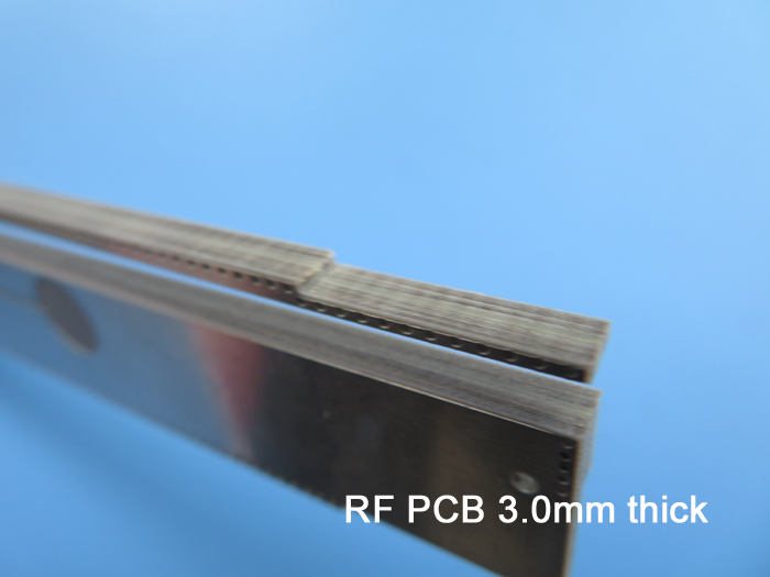
The F4B PTFE PCB Unleashes a New Era of Performance and Reliability Introduction In the fast-paced world of technology and electronics, advancements are constantly being made to meet the growing demands of high-performance devices. One such remarkable innovation is the F4B PTFE PCB, a cutting-edge printed circuit board that is set to revolutionize the industry. With its exceptional material properties and superior electrical performance, this state-of-the-art PCB is poised to redefine the standards of electronic design and manufacturing. Understanding F4B PTFE PCB The F4B PTFE PCB, short for fluorinated polytetrafluoroethylene printed circuit board, is a game-changer in the field of PCB technology. It is constructed using a specialized type of PTFE material that offers remarkable electrical properties and outstanding performance. Unlike traditional FR-4 PCBs, which use epoxy as the dielectric material, the F4B PTFE PCB employs PTFE. This unique choice of material brings a host of advantages, including low loss tangent, excellent impedance control, and exceptional signal integrity. One of the standout features of the F4B PTFE PCB is its ultra-low dielectric constant. With a typical value of around 2.2 to 2.4, it ensures reliable signal transmission and minimal signal distortion at high frequencies. This property makes it ideal for applications requiring high data transfer rates and high-speed signal processing. Furthermore, the F4B PTFE PCB exhibits extremely low loss tangent, typically below 0.001, which contributes to its outstanding electrical performance. This low loss tangent ensures minimal signal attenuation, making it perfect for demanding applications where signal integrity is critical. Unmatched Performance and Reliability The exceptional performance of the F4B PTFE PCB extends to its impressive thermal and mechanical properties. Its high glass transition temperature (Tg) of over 200°C ensures excellent stability and reliability in harsh operating conditions, preventing issues like signal distortion and material degradation. The F4B PTFE PCB also excels in thermal conductivity, effectively dissipating heat generated by high-power components. This feature is essential for maintaining optimal performance and preventing overheating, especially in applications where power-efficient designs are crucial. Mechanically, the F4B PTFE PCB offers excellent dimensional stability, even in extreme temperatures. This stability ensures consistent performance and reliable PCB assembly, reducing the risk of warping or other mechanical issues. Another notable advantage of the F4B PTFE PCB is its low moisture absorption rate. With a moisture absorption level of less than 0.05%, it ensures exceptional reliability and performance in humid environments, making it suitable for a wide range of applications. Diverse Applications and Future Prospects The F4B PTFE PCB's exceptional properties and performance make it highly versatile, enabling its use in numerous ap...
Categories
New Products

12-layer TG200 TU-872 SLK High-Speed FR4 1.68mm PCB with ENIG Impedance Control

12-Layer RO4350B + RO3010 3.14mm Hybrid PCB Nickel-Free EPIG Surface Finish Blind Via
8-Layer Hybrid PCB RO4003C + S1000-2M FR4 with ENIG Surface Finish Blind Via
6-Layer Isola Astra MT77 PCB with Blind Via & Resin Plug Immersion Silver Finish

2-Layer 20mil FSD1020T ENIG High-Frequency PCB with Via Resin Plugged and Capped

4-Layer F4BM265+S1000-2M Material Hyrbid PCB with Blind Via Impedance Control & ENIG

4-Layer Wangling WL-CT338 + FR4 Hybrid PCB ENIG Green Solder Mask White Silkscreen

6-layer Isola 370HR High-Tg FR-4 PCB 2μ" ENIG Impedance Controlled
 6-11C Shidai Jingyuan, Fuyong, Baoan, Shenzhen, Guangdong, China 518103


For inquiries about our products or pricelist, please leave to us and we will be in touch within 24 hours.
© Copyright: 2026 Shenzhen Bicheng Electronics Technology Co., Ltd.. All Rights Reserved.

IPv6 network supported


