
 Call Us Now !
Tel : +86 755 27374946
Call Us Now !
Tel : +86 755 27374946
 Order Online Now !
Email : info@bichengpcb.com
Order Online Now !
Email : info@bichengpcb.com
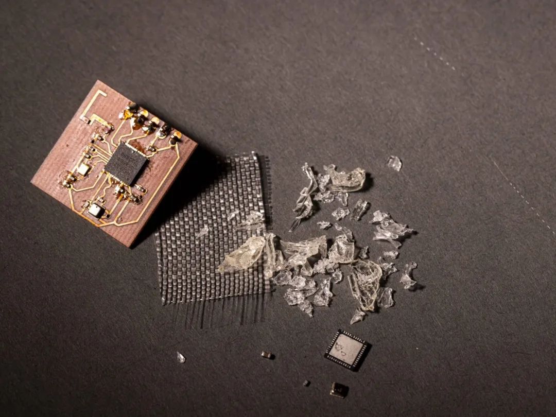
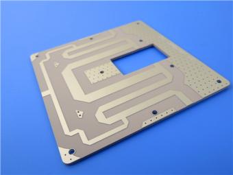
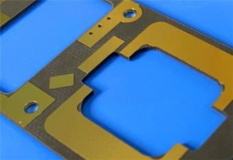
Researchers Have Developed New PCB Materials That Can Achieve Over 90% Raw Material Recovery The University of Washington research and development team recently announced that it has successfully developed a new type of PCB called vPCB. vPCB is made of Vitrimer-like polymer (Vitrimer) material, which has comparable electrical properties to traditional PCBS, while achieving a raw material recovery rate of over 90%. The left side is vPCB, the middle is glass fiber layer, and the right side is recycled vitreous polymer material. Photo source University of Washington official website, the samepicturebelow Traditional PCBS are usually composed of glass fiber reinforced epoxy resin laminates covered with copper foil. After PCB waste, it is difficult to separate the epoxy resin from the glass fiber. This hinders the recycling of PCB materials and increases the difficulty of e-waste reuse. The team at the University of Washington has successfully developed a vitreous polymer material. The material can replace the epoxy resin in the PCB, and at the same time, it can be converted into a jelly-like substance by a special solvent, which can be separated and recycled from the PCB. ▲ Vitreous polymer material removed with tweezers The team claims to have achieved 98% recovery of vitreous polymer, 100% recovery of glass fiber and 91% recovery of solvent. Less than a decade old, this class of vitreous polymers, first developed in 2015, have "dynamic covalent bonds" that reversibly crack and recombine when exposed to specific environments. In addition to the ease of recycling, VPCBS using vitreous polymer-like polymers have other unique advantages: due to their reconfigurable properties, VPCBS that bend or crack can be repaired in specific environments. The University of Washington said in a related article that the production of VPCBS does not require major adjustments to the PCB manufacturing process.
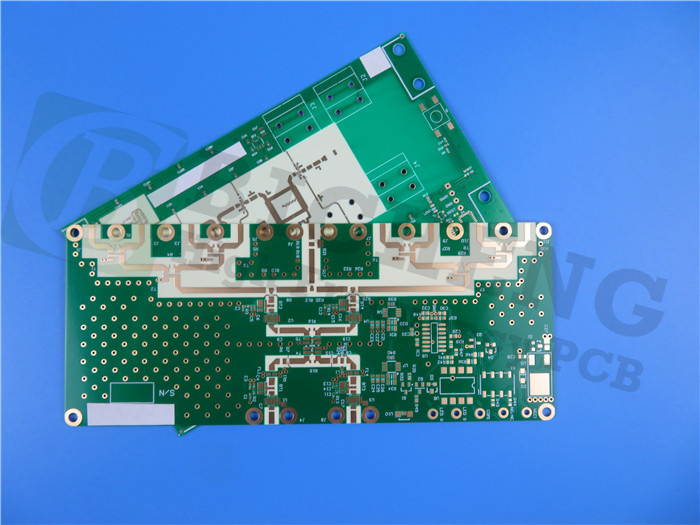
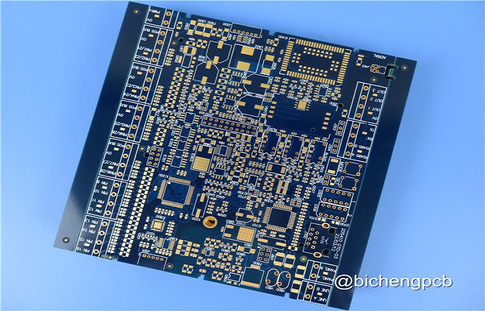
RO4360G2 PCB 20mil: Empowering the Growing Demand in the PCB Industry As the backbone of electronic products, PCBs play a pivotal role in various consumer electronics, such as computers and mobile phones. With the surge in digital economy, 6G technology, and artificial intelligence applications, the industry anticipates a significant boom in PCB demand. The Importance of PCBs in the Electronics Industry PCBs serve as crucial components for establishing electrical connections within electronic circuits. The vast array of downstream applications includes communication systems, computers, and automotive electronics, which collectively account for over 70% of PCB consumption. In fact, every aspect of information generation, processing, transmission, and application heavily relies on PCBs. According to industry insiders, the order visibility for PCB and IC substrate production equipment has been extended to 2024. Founder Securities highlights that the continuous growth of capital expenditures in global data centers has intensified the demand for PCBs. The rapid advancement of technology has led to the constant upgrading of traditional server PCBs, while the increasing deployment of artificial intelligence servers has propelled the demand for high-value single-machine PCBs. It is projected that the server PCB market size will reach an impressive US$16 billion by 2026. Market Growth and Future Prospects The research report by East Asia Qianhai Securities suggests that the demand for PCBs in the communication sector will remain stable in the long term. Additionally, the data center and automotive fields are expected to witness high demand. Consequently, the global PCB market is projected to experience an average annual compound growth rate of 4.8% from 2023 to 2026. By 2026, the global PCB market's output value is estimated to reach a staggering US$101.5 billion. Introducing RO4360G2 PCB 20mil Bicheng Company proudly presents the RO4360G2 PCB 20mil, a state-of-the-art solution designed to meet the ever-increasing demands of the PCB industry. The RO4360G2 high frequency laminates are low loss, glass-reinforced, hydrocarbon ceramic-filled thermoset materials that offer an optimal balance of performance and processing capability. This groundbreaking innovation represents the first high dielectric constant (Dk) thermoset laminate that can be processed similarly to FR-4. Key Features of RO4360G2: Dielectric Constant: The RO4360G2 boasts a dielectric constant of 6.15+/- 0.15 at 10 GHz/23°C, ensuring excellent signal integrity and electrical performance. Dissipation Factor: With a dissipation factor of 0.0038 at 10 GHz/23°C, this laminate minimizes energy loss and ensures efficient signal transmission. High Thermal Conductivity: The RO4360G2 offers a high thermal conductivity of 0.75 W/mK, facilitating effective heat dissipation and thermal management. Superior Dimensional Stability: It exhibits a l...
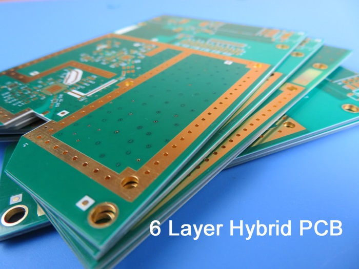
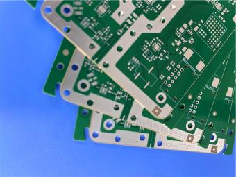
Global PCB Industry Shows Resilience Amidst Challenging Times Despite the challenges faced by the global PCB industry, the Prismark report reveals promising trends and growth prospects. In 2023, the industry experienced a 15.0% year-on-year decrease in output value in U.S. dollars. However, experts project a steady growth trajectory in the medium to long term. The compound annual growth rate for global PCB output value from 2023 to 2028 is expected to reach 5.4%. Regional Growth and Product Structure: The PCB industry's growth is not limited to a specific region but spans all corners of the globe. Mainland China has emerged as a significant player, with a compound growth rate of 4.1%. Looking at the product structure, packaging substrates, high-multilayer boards with 18 layers and above, and HDI boards are set to experience substantial growth in the next five years. These segments are projected to achieve compound growth rates of 8.8%, 7.8%, and 6.2%, respectively. Driving Factors for Packaging Substrate Products: Packaging substrate products are witnessing increased demand due to two primary factors. Firstly, the technological advancements and expanding application scenarios, such as artificial intelligence, cloud computing, smart driving, and the Internet of Everything, are driving the electronics industry's need for high-end chips and advanced packaging. This sustained growth is particularly notable in high-computing power and integration scenarios. Secondly, the government's increased support for the semiconductor industry, coupled with additional investments, is accelerating the development of the domestic packaging substrate industry. As terminal manufacturers' semiconductor inventories normalize, the global semiconductor market is predicted to grow by 13.1% in 2024, according to the World Semiconductor Trade Statistics Organization (WSTS). Growth Drivers for PCB Products: PCB products are propelled by the demand from various markets, including servers and data storage, communications, new energy and smart driving, and consumer electronics. The rapid evolution of artificial intelligence and the increasing need for high computing power and high-speed networks in the ICT industry are fueling the demand for large-size, high-level, high-frequency, high-speed, high-end HDI, and high-heat dissipation PCB products. The application of AI in mobile phones, PCs, smart wearables, IoT, and other products is driving the explosive growth of edge computing capabilities and high-speed data exchange. Consequently, terminal electronic equipment requires high-frequency, high-speed, integrated, miniaturized, light and thin, and high heat dissipation PCB products. Introducing the Hybrid PCB RO4003C High Tg FR-4 6-layer 2.24mm: To meet the growing demand for high-frequency applications,Bichengpresents the Hybrid PCB RO4003C High Tg FR-4 6-layer 2.24mm. This innovative product combines Tg170 FR-4 and 20mil RO4003C m...
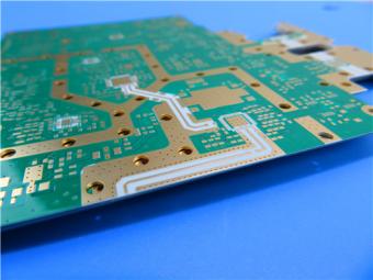
Analysis of the High-Speed PCB Industry Introduction: The high-speed PCB industry plays a pivotal role in meeting the increasing demand for electronic devices capable of handling high-frequency signals and data transmission. This analysis provides an in-depth exploration of the high-speed PCB industry, including its market dynamics, technological advancements, challenges, and future prospects. Market Dynamics 1)Growing Demand The demand for high-speed PCBs is driven by various factors, including the rapid growth of technologies such as 5G wireless communication, Internet of Things (IoT), cloud computing, artificial intelligence (AI), and autonomous vehicles. These applications require high-performance electronic devices that can reliably transmit and process data at high speeds. 2)Communication Infrastructure The deployment of 5G networks is a significant driver for the high-speed PCB industry. The implementation of 5G requires advanced communication infrastructure, including base stations, antennas, and network equipment, which heavily rely on high-speed PCBs. The demand for faster data rates, reduced latency, and increased bandwidth necessitates the use of high-speed PCBs to ensure reliable signal integrity. 3)Automotive Electronics The automotive industry is another key driver of the high-speed PCB market. The integration of electronic systems for advanced driver assistance systems (ADAS), infotainment systems, radar systems, and electric vehicle powertrains requires high-speed PCBs to handle the increased data processing and communication requirements. The shift towards electric vehicles and autonomous driving technologies further fuels the demand for high-speed PCBs in this sector. 4)Miniaturization and High-Density Interconnects The continuous drive for smaller and lighter electronic devices with increased functionality has led to the miniaturization of components and the need for high-density interconnects. High-speed PCBs with smaller form factors, high-density routing, and advanced technologies like microvias and high-density interconnect (HDI) are essential to accommodate the miniaturization trend while maintaining signal integrity and performance. Technological Advancements 1)Advanced Materials High-speed PCBs require materials with excellent electrical properties, such as low dielectric constant and low loss tangent, to minimize signal loss and maintain signal integrity. Materials like FR-4, PTFE (Polytetrafluoroethylene), and specialty laminates are commonly used. The development of new materials with improved electrical characteristics is an ongoing focus in the industry. 2)Controlled Impedance and Signal Integrity Maintaining controlled impedance is critical in high-speed PCB design to minimize signal reflections, crosstalk, and electromagnetic interference (EMI). Designers employ techniques like controlled trace widths, controlled dielectric thickness, differential signaling, and optimized ground planes to ensure signal integrity ...
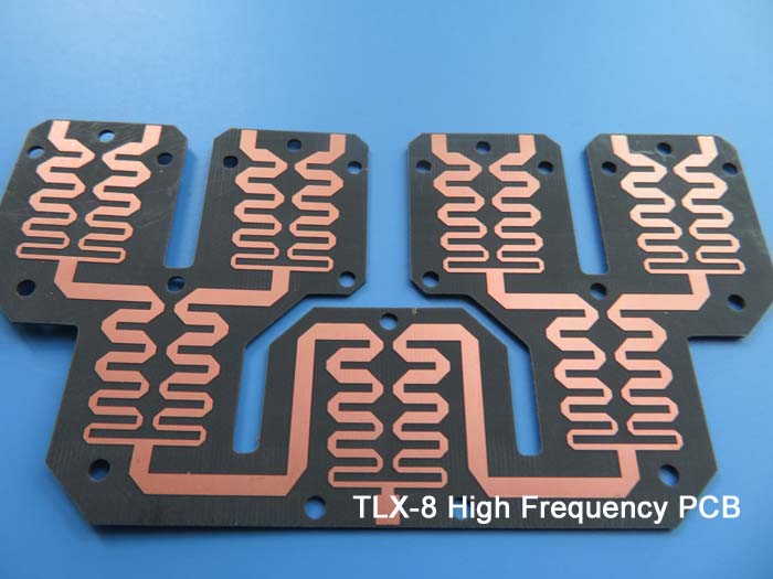
Advancements in PCB Manufacturing Propel Industry into New Frontiers The PCB industry is undergoing a transformative phase, driven by groundbreaking advancements and cutting-edge technologies that are propelling the industry into new frontiers. Miniaturization and High-Density Interconnects: The demand for smaller, lighter, and more powerful electronic devices continues to rise. To meet these evolving needs, PCB manufacturers are pushing the boundaries of miniaturization and high-density interconnects. Advanced fabrication techniques such as microvias, blind vias, and buried vias, along with finer trace and space requirements, enable the creation of compact PCB designs with enhanced functionality, enabling the next generation of consumer electronics, wearable devices, and IoT applications. Flexible and Rigid-Flex PCBs: Flexible and rigid-flex PCBs are witnessing a surge in popularity due to their ability to conform to complex shapes and provide greater design flexibility. With the advent of flexible substrates and advanced assembly techniques, PCB manufacturers are delivering innovative solutions for applications in industries such as automotive, aerospace, medical, and consumer electronics. The integration of flexible and rigid sections eliminates the need for connectors, reducing assembly time, improving reliability, and enabling new product form factors. High-Speed and High-Frequency PCBs: The relentless pursuit of faster data transfer rates and increased signal integrity has spurred advancements in high-speed PCB and high-frequency PCB technologies. Designers and engineers are leveraging specialized materials, controlled impedance routing, and advanced signal integrity analysis to achieve optimal performance in applications such as telecommunications, data centers, automotive radar systems, and 5G infrastructure. These advancements enable the efficient transmission of high-speed digital signals and the handling of ever-increasing frequencies. Advanced Materials and Substrates: The availability of advanced materials and substrates is revolutionizing the PCB industry. Next-generation materials, such as high-frequency laminates, high-speed digital materials, and thermally conductive substrates, offer improved electrical performance, signal integrity, thermal management, and reliability. These materials enable the design and manufacture of PCBs that can withstand demanding operating conditions, including high temperatures, high-frequency signals, and power dissipation requirements. We are thrilled to announce the global availability of 31mil TLX-8 PCB, a PTFE fiberglass laminate renowned for its unrivaled reliability and versatility. Taconic TLX-8 PCB as a game-changer in the PCB industry, offering engineers and designers an exceptional high-volume antenna material to power their RF applications. With a wide range of available thicknesses and copper cladding options, TLX-8 high frequency PCB proves itself indispensable in low layer count microwav...

Categories
New Products
6-Layer Isola Astra MT77 PCB with Blind Via & Resin Plug Immersion Silver Finish

2-Layer 20mil FSD1020T ENIG High-Frequency PCB with Via Resin Plugged and Capped

4-Layer F4BM265+S1000-2M Material Hyrbid PCB with Blind Via Impedance Control & ENIG

4-Layer Wangling WL-CT338 + FR4 Hybrid PCB ENIG Green Solder Mask White Silkscreen

6-layer Isola 370HR High-Tg FR-4 PCB 2μ" ENIG Impedance Controlled
6-Layer RO4003C + FR4 Mixed Dielectric PCB with Hard Gold Plating Blind Via
30mil Taconic CER-10 2-layer Immersion Silver DK10 High Frequency Laminate PCB
31mil Rogers RT/duroid 5880 Double-sided Bare Copper ENIG Finished PCB
 6-11C Shidai Jingyuan, Fuyong, Baoan, Shenzhen, Guangdong, China 518103


For inquiries about our products or pricelist, please leave to us and we will be in touch within 24 hours.
© Copyright: 2026 Shenzhen Bicheng Electronics Technology Co., Ltd.. All Rights Reserved.

IPv6 network supported


