
 Call Us Now !
Tel : +86 755 27374946
Call Us Now !
Tel : +86 755 27374946
 Order Online Now !
Email : info@bichengpcb.com
Order Online Now !
Email : info@bichengpcb.com
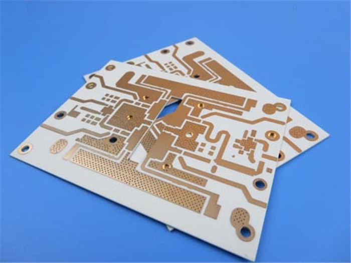
RF-10 10mil PCB: Revolutionizing High-Frequency Circuitry in a Rapidly Evolving PCB Industry Introduction: In the ever-evolving world of electronic devices and technology, printed circuit boards (PCBs) play a crucial role in enabling seamless connectivity and efficient performance. As the demand for high-frequency applications continues to grow, the PCB industry is witnessing significant advancements and innovations. Among these, the RF-10 10mil PCB stands out as a groundbreaking product that promises to revolutionize high-frequency circuitry. Advanced Material Technology: The RF-10 PCB is crafted using ceramic-filled PTFE (Polytetrafluoroethylene) and woven fiberglass, which have emerged as preferred materials for high-frequency applications. Combining the low dielectric constant and loss tangent properties of PTFE with the strength and rigidity of fiberglass results in a PCB that offers enhanced durability and reliability. With the industry placing greater emphasis on performance and longevity, the RF-10 PCB is designed to meet these evolving demands. Miniaturization and Compact Designs: One of the key trends shaping the PCB industry is the ongoing drive for miniaturization and compact designs. As electronic devices become smaller and more portable, the need for PCBs to occupy less space and deliver optimal performance has become paramount. The Taconic RF-10 PCB addresses this demand through its Dielectric Constant of 10.2 at 10GHz, allowing for RF circuit size reduction without compromising signal integrity. This capability makes it ideal for applications where smaller form factors are desired, such as wearable technology, Internet of Things (IoT) devices, and mobile communications. High-Speed Signal Transmission: In a world driven by data and connectivity, high-speed signal transmission is essential for seamless communication and efficient operations. The RF-10 PCB excels in this aspect, with a low Dissipation Factor of 0.0025 at 10GHz. This low loss tangent ensures minimal energy loss during signal transmission, enabling reliable and efficient high-speed data transfer. As industries like telecommunications, aerospace, and automotive continue to push the boundaries of high-speed applications, the RF-10 PCB becomes a critical component in achieving their goals. Thermal Management: As electronic devices become more powerful and compact, the issue of heat dissipation has become increasingly important. In high-frequency applications, efficient thermal management is crucial to maintaining optimal performance and preventing thermal damage. The RF-10 10mil substrate stands out in this regard, thanks to its high thermal conductivity. This property allows for effective heat dissipation, keeping electronic components cool and ensuring reliable operation even in demanding conditions. With applications ranging from microstrip patch antennas to satellite components, the RF-10 PCB provides a reliable solu...

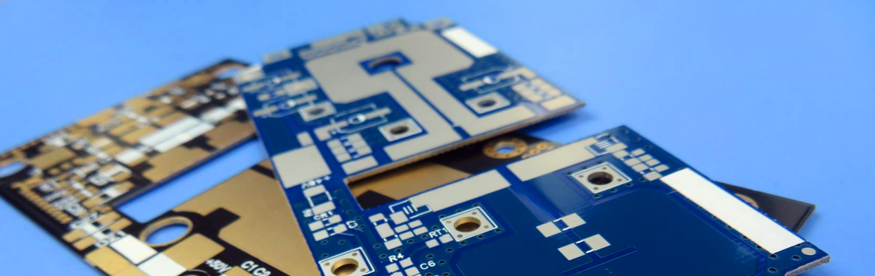
High-Frequency PCBs: Revolutionizing the Electronics Industry in 2023 In the fast-paced world of electronics, innovation is a driving force that propels the industry forward. As we enter 2023, high-frequency PCBs have emerged as a hot topic, transforming the way we design and manufacture electronic devices. These specialized circuit boards are at the forefront of technological advancements, enabling enhanced performance and paving the way for revolutionary applications across various sectors. High-frequency PCBs, also known as RF PCBs (Radio Frequency) or microwave PCBs, are specifically designed to handle signals in the radio frequency range. These boards are engineered with materials and construction techniques that minimize signal loss and distortion, allowing for efficient transmission and reception of high-frequency signals. They find application in a wide range of industries, including telecommunications, aerospace, automotive, and medical, among others. One of the key drivers of the high-frequency PCB market in 2023 is the relentless demand for faster and more reliable wireless communication. With the advent of 5G technology, the need for high-speed data transfer and low latency has skyrocketed. High-frequency PCBs play a critical role in enabling the development of advanced wireless infrastructure and devices, ensuring the seamless integration of 5G networks into our daily lives. Furthermore, the proliferation of Internet of Things (IoT) devices has created a surge in demand for high-frequency PCBs. As billions of devices become interconnected, the need for efficient communication and data processing at high frequencies becomes paramount. High-frequency PCBs enable the miniaturization and integration of complex IoT devices, facilitating seamless connectivity and interactivity. In addition to telecommunications and IoT, high-frequency PCBs are also revolutionizing other industries. In the automotive sector, these boards are being utilized in advanced driver-assistance systems (ADAS) and autonomous vehicles to enable reliable and high-speed communication between various sensors and control units. In the aerospace industry, high-frequency PCBs are crucial for satellite communication systems and radar technology, ensuring precision and accuracy in data transmission. As the demand for high-frequency PCBs continues to grow,suppliers are focusing on developing advanced materials and manufacturing techniques. One such breakthrough is the introduction of the RT/duroid 6010.2LM ceramic PTFE composites by Bicheng PCB. This high-frequency PCB material offers exceptional performance and reliability, revolutionizing circuit design and opening new doors for various applications. The 50mil RT/duroid 6010.2LM boasts an impressive dielectric constant of 10.2 at 10 GHz and a dissipation factor of 0.0023 at the same frequency. These remarkable properties make it an ideal choice for applications operating at X-...

2023 Mid-Autumn Festival and National Day Holiday Notice -RO4003C 20mil Rogers PCB: High Performance and Reliability Dear valued customers and partners, We are pleased to announce that Bicheng Company will be taking a 7-day holiday break in celebration of the Mid-Autumn Festival and National Day from September 29th to October 5th, 2023. During this time, our office will be closed, and normal operations will resume on October 6th, 2023. The Mid-Autumn Festival, also known as the Moon Festival, is one of the most important traditional Chinese festivals, symbolizing family reunion and harvest. It falls on the 15th day of the eighth lunar month, which this year coincides with September 30th, 2023. This festival is celebrated by gathering with family and friends, appreciating the full moon, and indulging in delicious mooncakes. Following the Mid-Autumn Festival, China's National Day, which commemorates the founding of the People's Republic of China, is celebrated on October 1st, 2023. This holiday marks a significant period of national pride and unity. During this holiday break, we encourage you to take this opportunity to spend quality time with your loved ones and create precious memories. We sincerely apologize for any inconvenience caused by the temporary closure and appreciate your understanding. Should you have any enquiry during the holidays, pls feel free to email to j.shi@bichengpcb.com. Best regards, Shenzhen Bicheng Electronics Technology Co., Ltd In addition to our holiday announcement, we would like to take this opportunity to introduce our new product, the PCB Material. This cutting-edge material offers exceptional performance and reliability, making it an excellent choice for a wide range of applications. Here are some key features and benefits: RO4003C 20mil Rogers PCB: High Performance and Reliability Experience the power of advanced technology with our newly shipped RO4003C 20mil Rogers PCB. Engineered with precision and designed for performance-sensitive, high-volume applications, this PCB is a game-changer in the world of electronic circuitry. Let's delve into the remarkable features and benefits that make this PCB stand out from the rest. 1. PCB Material: Crafted from Rogers RO4003C Hydrocarbon Ceramic woven glass, our PCB boasts unparalleled quality. With a 4003C Dielectric Constant (DK) of 3.38 at 10 GHz and a Dissipation Factor of 0.0027 at 10GHz, it ensures low dielectric tolerance and low loss. The impressive Tg (>280 °C) and Td (>425°C) ratings enable reliable operation in temperature ranges from -40℃ to +85℃. 2. Features and Benefits: A) Reinforced Hydrocarbon/Ceramic Laminates: Our RO4003C Rogers material is a hydrocarbon/ceramic laminate, distinct from PTFE alternatives. This unique composition offers exceptional electrical performance and stability, making it perfect for high-frequency applications. B) Excellent Electrical Performance: With its low dielectric tolerance and low loss, our PCB delivers outst...
Introducing the Game-Changing RO3203 PCB, Redefining the High-Frequency PCB Industry In the rapidly evolving world of high-frequency PCBs, a groundbreaking announcement has been made with the introduction of the revolutionary RO3203 PCB. This state-of-the-art technology is set to redefine performance and reliability standards in the industry, catering to the growing demands of various sectors such as 5G, aerospace, and automotive. The Rogers RO3203 PCB boasts a meticulously engineered design, combining ceramic-filled PTFE reinforced with woven fiberglass material. With an impressive dielectric constant (DK) of 3.02 at 10 GHz/23°C, it ensures flawless signal integrity and minimal loss. Its low dissipation factor of 0.0016 at the same frequency and temperature range allows for efficient transmission of high-frequency signals. This PCB also offers extraordinary thermal stability, withstanding temperatures up to 500°C, making it ideal for demanding applications. The construction of the RO3203 PCB showcases exceptional durability and reliability. Its 2-layer rigid structure features copper layers on both sides and utilizes a 0.762 mm 30mil RO3203 substrate. The well-engineered stackup ensures optimal performance, while the 1 oz (1.4 mils) outer layer copper weight enhances conductivity. With a finished board thickness of 0.89mm, green solder masks on both sides, and an immersion gold surface finish, the RO3203 PCB combines both aesthetic appeal and functionality. To ensure top-notch quality, rigorous testing and comprehensive quality control measures are implemented. Each 30mil RO3203 material PCB undergoes a thorough 100% electrical test before shipment, meeting stringent industry standards. Exceeding expectations in terms of durability, longevity, and performance, this PCB complies with the IPC-Class-2 standard. It offers a wide range of connectivity options with its various through-hole pads, SMT pads, vias, and nets, catering to diverse industry needs. The demand for high-frequency PCBs is projected to surge due to the rapid growth of 5G technology, IoT applications, and the automotive sector. The introduction of the Rogers 3203 PCB addresses these emerging needs by providing exceptional performance and reliability. Its advanced features and specifications make it an ideal choice for high-frequency electronic designs. As the industry continues to evolve, it is essential to stay informed about the latest trends and advancements. The RO3203 high frequency PCB represents a monumental step forward for the high-frequency PCB industry, offering unmatched performance and reliability. For more information and technical support regarding the RO3203 PCB, reach out to the dedicated sales team at the provided contact address. In conclusion, the Rogers RO3203 PCB is a game-changer in the high-frequency PCB industry. Its cutting-edge technology, superior materials, and meticulous design set new benchmarks for performance and reliability. With its exceptional fe...
PCB in 2024 or Will Resume Growth According to analyst Zhang Yuansong from the Industrial Technology Research Institute (ITRI), the PCB industry is expected to resume growth in 2024. While the strength of the third-quarter peak season is still uncertain, the continuous destocking of consumer products and the ongoing momentum in the EV, AI server, and satellite communication sectors are expected to drive PCB output, with a potential rebound in 2024. ABF substrates will benefit from the expansion of advanced packaging, and the supply-demand gap is expected to widen in the next two years. Zhang Yuansong attended an IEK expert symposium organized by Yuanta Securities on August 28th. He believes that the automotive industry will be the only PCB terminal application with a year-on-year growth this year, especially with electric vehicles accounting for 14% to 15% of the overall automotive market. The increasing adoption of EVs will drive the demand and area of PCBs. If they can penetrate the supply chain of companies like Tesla and BYD, there will be a noticeable increase in orders in the next one to two years. Although multilayer boards accounted for 60% of the overall automotive PCB production value in the first half of this year, the increasing electrification and widespread adoption of ADAS will drive the application of HDI PCB boards in automotive radar and camera module systems. HDI and flexible boards will become the most promising segments in the automotive PCB market. Supply chain companies such as Kinwong, Unimicron, Dingying, and Jingpeng are expected to benefit from this trend. In the short term, Zhang Yuansong believes that the third quarter will see a peak season effect due to the launch of new Apple products. However, with the situation of high inflation and the recovery of mainland China not meeting expectations, the strength of the peak season remains to be observed. In 2022, the PCB industry achieved high growth, creating a higher base year for comparison. Therefore, the overall PCB output is expected to decline by 16.8% in 2023, reaching NT$769.3 billion. In 2024, driven by the synchronous recovery of mobile phones, laptops, and semiconductors, as well as the continued momentum in EVs, AI servers, and satellite communication, the overall PCB output is expected to return to growth, with an estimated annual growth rate of 8.1%. In particular, for ABF substrates, in order to meet the demand for advanced computing, chiplet heterogeneous integration packaging technology is the future trend. It can integrate chips from different fabs, different process nodes, and different properties into a single chip. This will drive the increase in the number of layers, area, and circuit density of ABF substrates, raising the manufacturing threshold. The demand for ABF substrates will be driven by advanced packaging spreading to various fields. From a situation of oversupply of 5% this year, it is expected t...
RO4003C Rogers 12mil High Frequency PCB-PCB Industry Experiences Rapid Growth in High-Frequency Applications Demand With the continuous advancement of technology, the demand for high-frequency applications has rapidly expanded across various industries. This unprecedented growth presents significant opportunities for the Printed Circuit Board (PCB) industry. High-frequency applications have become crucial technological requirements in fields such as communication, electronics, automotive, aerospace, and more, driving the rapid rise of the PCB industry. Meeting the demands of high-frequency applications requires PCB design, manufacturing, and performance to meet higher standards. Consequently, many PCB suppliers and technology providers have introduced solutions tailored for high-frequency applications.In order to change this situation, BICHENG also provide a new shipped 12mil Rogers RO4003C PCB Material for High-Frequency Applications. Here is our new shipped 12mil RO4003C PCB detailed information: Material Advancements: Rogers RO4003C stands out as a highly regarded Rogers PCB material for high-frequency applications. It utilizes woven glass reinforced hydrocarbon ceramic material, offering excellent signal integrity and low loss coefficients. With a dielectric constant of 3.38 at 10 GHz/23°C and a loss factor of just 0.0027, it effectively reduces signal attenuation. Additionally, RO4003C exhibits exceptional high-temperature resistance, ensuring stable operation across a wide temperature range. Rogers RO4003C PCB 12mil Material for High-Frequency Applications: Experience superior performance with our hydrocarbon ceramic woven glass material Processed with DK 3.38 at 10 GHz/23°C, ensuring optimal signal integrity Low dissipation factor of 0.0027 at 10 GHz/23°C for minimal signal loss Withstands high temperatures, boasting a Tg >280°C and Td >425°C Suitable for operation in a wide temperature range of -40℃ to +85℃ Boost Your RF Design with our12mil RO4003C2-layer Rigid PCB Stackup Utilizes Rogers 4003C substrate with a thickness of 0.305mm Copper layer thickness of 35μm on both the top and bottom layers Achieve precise trace and space requirements with a minimum of 4/4 mils Accommodates 0.25mm minimum hole size for various component needs Finished board thickness of 0.43mm for compact and lightweight designs Unveiling the Construction Details of our High-Quality PCB Board dimensions of 170.53mm x 180.35mm, offering flexibility for different applications A total of 115 components and 217 pads for comprehensive functionality Includes 112 through-hole pads and 105 top SMT pads for versatile component placement Vias totaling 168 for efficient signal routing and connection Adheres to IPC-Class-2 standard to ensure reliable and consistent quality Trustworthy Quality and Global Availability Each board undergoes a 100% electrical test before shipment, ensuring reliability Supplied wi...
Categories
New Products

12-layer TG200 TU-872 SLK High-Speed FR4 1.68mm PCB with ENIG Impedance Control

12-Layer RO4350B + RO3010 3.14mm Hybrid PCB Nickel-Free EPIG Surface Finish Blind Via
8-Layer Hybrid PCB RO4003C + S1000-2M FR4 with ENIG Surface Finish Blind Via
6-Layer Isola Astra MT77 PCB with Blind Via & Resin Plug Immersion Silver Finish

2-Layer 20mil FSD1020T ENIG High-Frequency PCB with Via Resin Plugged and Capped

4-Layer F4BM265+S1000-2M Material Hyrbid PCB with Blind Via Impedance Control & ENIG

4-Layer Wangling WL-CT338 + FR4 Hybrid PCB ENIG Green Solder Mask White Silkscreen

6-layer Isola 370HR High-Tg FR-4 PCB 2μ" ENIG Impedance Controlled
 6-11C Shidai Jingyuan, Fuyong, Baoan, Shenzhen, Guangdong, China 518103


For inquiries about our products or pricelist, please leave to us and we will be in touch within 24 hours.
© Copyright: 2026 Shenzhen Bicheng Electronics Technology Co., Ltd.. All Rights Reserved.

IPv6 network supported


