
 Call Us Now !
Tel : +86 755 27374946
Call Us Now !
Tel : +86 755 27374946
 Order Online Now !
Email : info@bichengpcb.com
Order Online Now !
Email : info@bichengpcb.com
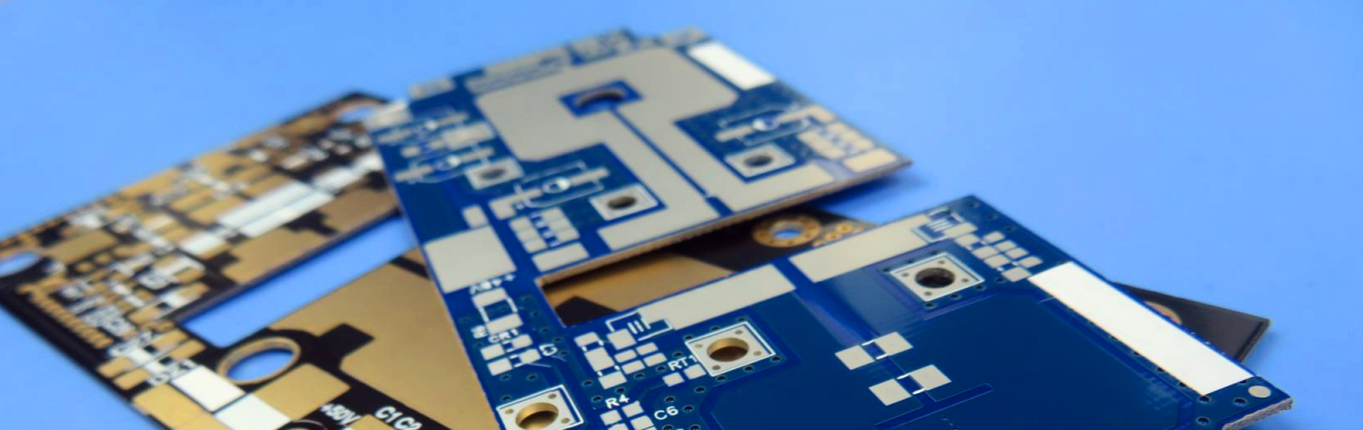
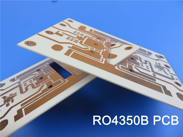
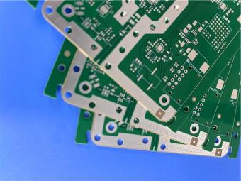
New High-Frequency PCB Material Enhances Wireless Communication System Performance In recent days, the high-frequency PCB industry has captured the attention of professionals, as a breakthrough product has been launched that promises significant advancements in the performance of wireless communication systems. This innovative new product utilizes cutting-edge material solutions to deliver a more efficient and reliable communication experience for users. The high-frequency PCB incorporates 30mil Rogers RO4350B hydrocarbon ceramic laminates, renowned for their excellent thermal conductivity and stability. With a lead-free process, the product meets environmental standards and addresses the growing consumer demand for eco-friendly materials. Furthermore, the operating temperature range of -40℃ to +85℃ ensures its suitability for a wide range of complex environments. Regarding construction details, the stackup of this high-frequencyRO4350B PCB involves a base copper layer of 17um, a 30mil RO4350B dielectric layer, and another 17um base copper layer. This design ensures the stability and reliability of high-frequency signals during transmission. Precise control over these construction details guarantees the quality of communication for users. In addition, the Rogers 4350B PCB boasts several outstanding features. The board dimensions measure 52.00mm x 38.00mm, with an accuracy of +/- 0.15mm, meeting the requirements for precise dimensions. With a minimum trace/space of 8/6 mils and a minimum hole size of 0.5mm, it fulfills the demands of high-density circuit designs. The product employs 1 oz (1.4 mils) finished copper weight across all layers, 1 mil via plating thickness, and an ENEPIG surface finish, further enhancing its quality and reliability. Notably, the high-frequency material PCB is equipped with a top and bottom solder mask of Matt Black, 0.5mm via copper paste filled and capped, and requires edge plating. These carefully implemented manufacturing processes contribute to exceptional electrical performance and stability. Impedance matching, accurate within +/- 10%, is achieved to ensure signal stability and consistency. Additionally, the product provides comprehensive statistics, including 15 components, 53 pads, 45 vias, and 3 nets, offering valuable reference information for users. For any technical inquiries regarding this high-frequency PCB technology, customers are encouraged to contact Jane, the sales manager, at sales20@bichengpcb.com, who will provide technical support and consultation services. The introduction of this groundbreaking 30mil RO4350B high-frequency PCB material will undoubtedly propel the development of wireless communication systems. Its outstanding performance and reliability will enhance the speed, stability, and reliability of wireless communication, delivering an exceptional communication experience for users. Looking ahead, we anticipate further innovations in the high-frequency PCB industry, unlocking mo...
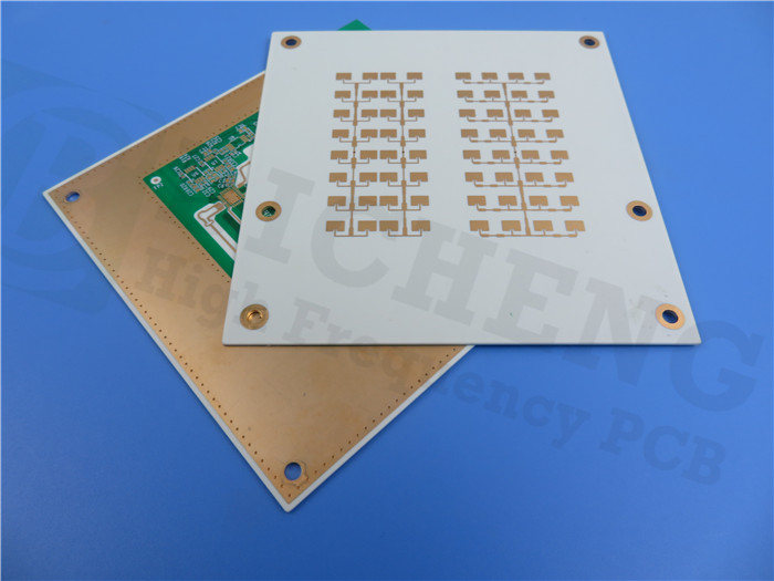
2024 Will Return to the Growth Track CCL ITEQ Optimistic About the Future Market of Vehicles ITEQ, a leading manufacturer of copper foil substrates (CCL), is making strides in the high-end automotive electronics sector as the demand for electric bikes and self-driving cars continues to grow. The company is positioning itself for success in this sector and remains optimistic about its operational performance. In the first half of 2023, ITEQ expects a slow recovery in consumer electronics demand due to destocking. Additionally, the transition period between new and old platforms for servers poses operational challenges. However,ITEQ anticipates that its high-end automotive electronics business will remain resilient, with double-digit revenue growth and a revenue proportion exceeding 20% in 2023. ITEQ is well-positioned to benefit from the increasing penetration rate of electric vehicles (EVs) and self-driving cars. The company expects a surge in production volume for HDI boards and high-speed materials used in autonomous driving systems, EVs, and Vehicle Computing-related applications in the coming years. This growth in the automotive business is expected to contribute to an increase in gross profit margin. Furthermore,ITEQ has successfully passed certification for materials used in multiple AI GPU servers, aligning with the increasing demand for high-end high-speed computation materials in data centers. With major cloud service providers accelerating their AI-related capital expenditures, there is a growing need for circuit boards with more layers and high-speed materials. This sustained demand is expected to support the long-term upgrading of the server industry. While the revenue recovery in the third quarter may be limited due to the delayed ramp-up of the Intel Eagle Stream platform,ITEQ is confident in its long-term growth plans. The company is committed to developing next-generation HDI/SLP materials and has partnered with leading Japanese material manufacturers to meet the future demand of the IC carrier board market. ITEQ expects to regain its growth trajectory in 2024 and remains optimistic about the future demand for high-end electronic materials. The company is prepared to adapt to changes in the global supply chain and has plans to expand its production facilities in China and Thailand. With its focus on innovation and meeting customer needs, Unimicron is poised to maintain its position as a leader in the high-end electronics industry. As part of its ongoing commitment to innovation,BICHENG is proud to announce its newly shipped product, the 20mil RO4350B material PCB. This advanced PCB material is designed for high-performance applications and offers a lead-free process and operation in a wide temperature range of -40℃ to +85℃. With a 2-layer rigid PCB stackup, the RO4350B Hydrocarbon Ceramic Laminates PCB provides excellent performance ...
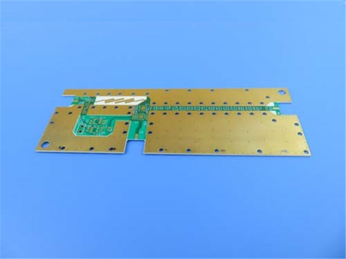
Introduces New High-Power PCBs to Meet Growing Automotive Industry Demands The launch of BICHENG's latest product line, specifically designed for the automotive industry, is pleased to be announced. As the demand for electric vehicles (EVs) and autonomous driving technologies continues to rise, BICHENG is taking the lead in providing high-quality PCB solutions to meet these evolving needs. With the global economic downturn impacting the terminal market, cautious optimism has been expressed by automotive customers for the remainder of 2023. However, it is believed by industry giant Jingpeng that the situation will improve in the second half of the year, aligning with the expectations of a stable market from July to August. This opportunity is recognized by BICHENG, who is prepared to support the automotive industry with their innovative PCB materials and construction. The new PCB material, the 60mil RO4534 high frequency PCB, being offered by BICHENG, boasts a DK 3.4 rating. This high-performance material is capable of operating in temperatures ranging from -40℃ to +85℃, making it ideal for the demanding environments of automotive applications. Additionally, compliance with environmental regulations is ensured by BICHENG's lead-free process while maintaining exceptional quality. The 2-layer 60mil RO4534 rigid PCB stackup provided by BICHENG features finished copper of 35um with a RO4534 dielectric thickness of 60 mil (1.524mm). Optimal performance and durability for automotive PCBs are ensured by this construction detail. RO4534's commitment to precision can be seen in their adherence to strict tolerances, including a minimum trace/space of 4/4 mils and a minimum hole size of 0.4mm. BICHENG's dedication to delivering reliable solutions is further highlighted by their PCB statistics. With 173 components, 200 total pads, and 161 vias, RO4534 PCBs are designed to meet the most demanding automotive requirements. Exceptional quality and reliability are guaranteed by the company's adherence to the IPC-Class-2 standard. As the demand for high-power automotive products, such as power control units (PCUs), intelligent power modules (IPMs), and battery management systems (BMS), continues to grow, the need for thick copper PCBs becomes paramount. This trend is recognized by BICHENG, who has focused on developing PCBs capable of withstanding high temperatures, high voltages, and large currents. These PCBs are particularly suitable for high-power-consuming products such as EV charging stations and high-frequency communication base stations. BICHENG's position as a leading provider in the automotive industry is strengthened by their investment in the development of thick copper PCBs. With extensive experience in small-scale and diversified business models, BICHENG is prepared to meet the increasing demand for high-wattage, multifunctional charging devices, and newly launched EV models in 2023. To learn more about BICHENG's high-power PCBs and how they...
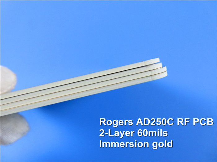
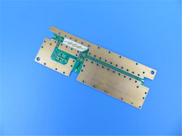
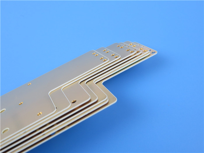
Consumer Electronics and Automotive Electronics: The Driving Force of PCB Demand The Printed Circuit Board (PCB) industry is crucial to the electronics manufacturing industry, with PCBs serving as the foundation for all electronic devices. The PCB industry's supply chain consists of upstream raw material suppliers, midstream PCB manufacturers, and downstream companies in fields such as communication, electronics, semiconductors, and computers. In recent years, the PCB industry has been in a "bottoming-out phase," with falling raw material costs and declining revenue and profit performance for major PCB manufacturers. However, the industry's long-term outlook remains positive, with the development trend shifting towards high-density and high-performance PCBs. BICHENG, a leading PCB supplier, has recently shipped a high-quality 2-layer rigid AD250C PCB with an immersion gold surface finish. The PCB utilizes AD250C woven glass reinforced PTFE with a dielectric of 60 mil and finished copper of 70um. The lead-free process and -40℃ to +85℃ operation make it ideal for use in a wide range of electronics applications. The PCB meets IPC-Class-2 standards and 100% electrical test requirements, ensuring optimal performance and reliability. The PCB industry's raw material costs, including copper foil, epoxy resin, and fiberglass cloth, have been falling, creating opportunities for PCB manufacturers to reduce costs and improve profitability. However, the industry's recovery will depend on downstream demand picking up and new demand growth points emerging. Consumer electronics and automotive electronics are expected to drive the demand for PCB, with the recovery of consumer electronics and the innovation of segmented products, and the development of intelligent automotive electrification. Domestic PCB suppliers, including BICHENG, are expanding production and focusing on high-density and high-performance PCBs, which aligns with the industry's development trend. The expansion plans of major manufacturers mainly focus on HDI boards, IC packaging substrates, and high-layer boards. The primary downstream applications of the PCB industry include computers, communication, and consumer electronics, among other areas. With the rapid development of the global consumer electronics industry, new consumer hotspots such as smartphones, tablets, and wearables will continue to emerge, increasing demand for high-quality PCBs. BICHENG's newly shipped 60MIL AD250C PCB is a testament to the company's commitment to quality and sustainability. The use of woven glass reinforced PTFE as the PCB's material contributes to optimal performance and durability, while the lead-free process ensures sustainable manufacturing. The immersion gold surface finish provides excellent corrosion resistance and ensures superior solderability, making it an ideal choice for electronics manufacturers. In conclusion, the PCB industry is facing both challenges and ...
How Automotive PCBs Differ from Ordinary PCBs? The automotive industry is constantly evolving, with new technologies and innovations being introduced every year. One area that has seen significant advancements is automotive electronics. From infotainment systems to advanced driver assistance systems (ADAS), modern cars are becoming more reliant on electronics. However, these systems are only as good as the printed circuit boards (PCBs) that power them. In this article, we will explore the importance of quality and reliability in automotive PCBs. Material Selection: FR-4 HTG and Polyimide One of the key differences between automotive PCBs and ordinary PCBs is the materials used. While ordinary PCBs typically use FR-4 fiberglass material, automotive PCBs require higher-level materials such as FR-4 HTG or polyimide materials that have better high-temperature tolerance. This is because automotive PCBs need to have better stability and reliability in high-temperature environments. Process Requirements: Strict Soldering and Protection Treatment Automotive PCBs also require stricter soldering and protection treatment to ensure circuit stability and reliability. The more severe working environment and vibration impact that automotive PCBs need to withstand means their process requirements are higher. This includes more rigorous testing and quality control measures. Environmental Adaptability: High-Temperature Resistance and Anti-Vibration Capabilities Automotive PCBs need to adapt to more complex automotive working environments, such as high temperature, low temperature, humidity, and vibration. Therefore, automotive PCBs need to have better high-temperature resistance, humidity resistance, and anti-vibration capabilities. This ensures that the PCBs can function properly in a variety of conditions, which is crucial for the reliability of automotive electronics. Reliability: Anti-Aging, Anti-Corrosion, and Anti-Interference Because automotive PCBs play a more important role in automotive electronic systems, their reliability requirements are higher. Automotive PCBs need to withstand long-term work and severe working environments, and therefore require better anti-aging, anti-corrosion, and anti-interference capabilities. Additionally, automotive PCBs need to undergo strict reliability testing to ensure their stability and reliability under various extreme conditions. Advancements in Automotive PCB Materials As automotive electronics continue to advance, so do the materials used in automotive PCBs. Manufacturers are now using new materials such as ceramic and metal core PCBs to meet the higher demands of the industry. These materials offer increased thermal conductivity and better heat dissipation, which is crucial for the reliability of automotive electronics. Meeting the Demands of the Automotive Industry At BICHENG, we understand the importance of quality and reliability in automotive PCBs. Our newly shipped PCBs use Rogers RO4350B material, which offer...
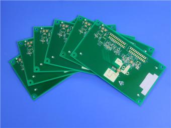
The Demand for This Type of PCB Is Hot, But… The PCB industry is experiencing a steady rise in output value, driven by increasing demand for AI server PCBs. AI server PCBs are a critical component of modern high-speed computing, requiring high-density wiring, high-speed signal transmission, low noise, and low interference. Technological advancements in chip and memory technologies are creating more growth opportunities in key component fields such as PCB. China has emerged as a global leader in PCB production, with the country's PCB output value accounting for approximately 69% of the world's total output value. China's developed and mature PCB industry is well-positioned to meet the demands of AI server PCB production. Analysts predict that the market size of AI server PCBs will reach $7.9 billion by 2025, with the global output value of the PCB industry expected to reach $98.388 billion by 2027. Manufacturing AI server PCBs poses unique challenges, requiring a high level of expertise and precision. The number of PCB layers, the width of the routing, and the size of the apertures are not related to the size of the PCB itself, making the process more complex. However, the potential rewards are significant, as the demand for AI server PCBs is expected to increase as technological advancements continue to drive the growth of high-speed computing. BICHENG's newly shipped PCB is a high-quality example of modern PCB manufacturing, using advanced materials and construction details. The double-sided PCB features 20mil Rogers RO4350B material, lead-free processing, and can operate in temperatures ranging from -40℃ to +85℃. The board dimensions are 80mm x 70mm, with a minimum trace/space of 9/10 mils and a minimum hole size of 12 mils. The board has no blind or buried vias, a finished board thickness of 0.58mm, and a finished Cu weight of 1 oz (1.4 mils) all layers. Via plating thickness is 1 mil, and the surface finish is immersion silver. The Rogers RO4350B PCB underwent a 100% electrical test, with a total of 27 components, 30 pads, 21 thru-hole pads, and 61 vias. The market demand for AI server PCBs is related to all aspects of the server industry chain and the overall technological level of the chain. While the prospects for the industry are promising, the market demand for AI server PCBs is not yet clear. The implementation of the demand side of the PCB market requires a process, which requires consideration of multiple factors such as overall market demand and company fundamentals. In conclusion, the future of PCBs is inextricably linked to the growth of artificial intelligence and high-speed computing. The development and application of cutting-edge technologies have increased the overall demand for AI servers, driving growth in key component fields such as PCB. While manufacturing AI server PCBs poses unique challenges, the potential rewards are significant. BICHENG's newly shipped RO4350B PCB is ...
Categories
New Products

12-layer TG200 TU-872 SLK High-Speed FR4 1.68mm PCB with ENIG Impedance Control

12-Layer RO4350B + RO3010 3.14mm Hybrid PCB Nickel-Free EPIG Surface Finish Blind Via
8-Layer Hybrid PCB RO4003C + S1000-2M FR4 with ENIG Surface Finish Blind Via
6-Layer Isola Astra MT77 PCB with Blind Via & Resin Plug Immersion Silver Finish

2-Layer 20mil FSD1020T ENIG High-Frequency PCB with Via Resin Plugged and Capped

4-Layer F4BM265+S1000-2M Material Hyrbid PCB with Blind Via Impedance Control & ENIG

4-Layer Wangling WL-CT338 + FR4 Hybrid PCB ENIG Green Solder Mask White Silkscreen

6-layer Isola 370HR High-Tg FR-4 PCB 2μ" ENIG Impedance Controlled
 6-11C Shidai Jingyuan, Fuyong, Baoan, Shenzhen, Guangdong, China 518103


For inquiries about our products or pricelist, please leave to us and we will be in touch within 24 hours.
© Copyright: 2026 Shenzhen Bicheng Electronics Technology Co., Ltd.. All Rights Reserved.

IPv6 network supported


