
 Call Us Now !
Tel : +86 755 27374946
Call Us Now !
Tel : +86 755 27374946
 Order Online Now !
Email : info@bichengpcb.com
Order Online Now !
Email : info@bichengpcb.com
2026 Labor Day Holiday Notice Dear Valued Customers and Partners, Greetings from Shenzhen Bicheng Electronics Technology Co., Ltd.! As the International Workers' Day approaches, we would like to express our sincere gratitude for your continuous trust and support. To help you plan your upcoming PCB orders and projects smoothly, please be informed of our 2026 Labor Day holiday schedule: Holiday Period: May 1st (Friday) to May 5th (Tuesday), 2026 We will resume normal business operations on Wednesday, May 6th, 2026. During the Holiday: While our office and factory will be closed, you can still reach us via email for any urgent matters or quotations. We will endeavor to check our inboxes periodically and respond to critical issues as promptly as possible. General Inquiries: info@bichengpcb.com For urgent technical support, feel free to reach out to your direct sales representative, and we will get back to you as soon as we can. We are astable PCBsupplierer in China, specializing in high-frequency boards, Rogers PCBs, F4B, and high-speed multilayer boards. With 18+ years of industry experience, we remain committed to providing you with high-quality PCBs and punctual delivery. Thank you for your understanding and patience. We wish you and your family a happy and restful Labor Day! Warmest regards, Shenzhen Bicheng Electronics Technology Co., Ltd. Web: www.bichengpcb.com | Email: info@bichengpcb.com
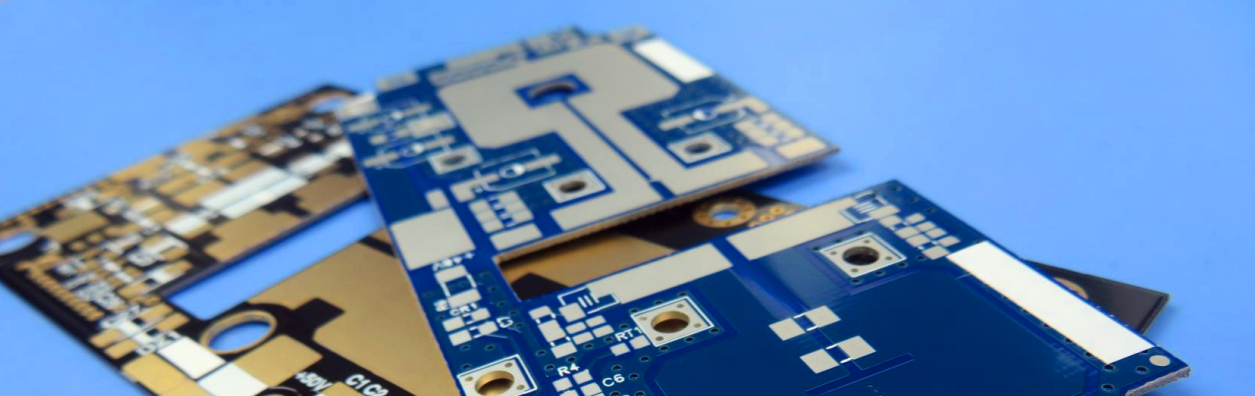
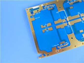
LEO Satellite Boom Sparks High-End "Arms Race" in PCB Supply Chain The market for low Earth orbit (LEO) satellite boards is gaining momentum, with leading PCB manufacturers racing to secure key positions. Recently, multiple companies in the industry chain have successively disclosed their progress, spanning technology reserves, capacity construction, and product supply—all signaling strong confidence in the sector's prospects. Regarding the current development of PCBs in LEO satellite applications, Zhang Yi, CEO and Chief Analyst at iiMedia Consulting, told Cailianshe reporters that the industry is transitioning from customized development to mass production on assembly lines. Leading companies have also achieved breakthroughs in technical bottlenecks, integrating into core supply chains such as Starlink and China StarNet. PCB industrial clusters for aerospace applications have emerged in the Pearl River Delta and Yangtze River Delta regions, offering robust support in terms of intelligent production lines, batch manufacturing, and delivery lead times. A senior executive from a listed PCB company told Cailianshe reporters that PCBs for LEO satellites have stringent requirements regarding high frequency and insertion loss. The company produces such products, which are expected to gradually ramp up production this year. To meet these demanding specifications, the supply chain has begun adopting high-performance materials. At Bicheng, we address these challenges with advanced material solutions. A typical 2-layer Rogers PCB stackup consists of 35μm copper layers on both sides of an AD300D substrate measuring 1.016 mm (40mil). Rogers AD300D is a ceramic-filled, glass-reinforced PTFE-based laminate engineered for today’s wireless antenna markets. It delivers a controlled dielectric constant (DK 2.94 at 10 GHz/23°C), low loss (dissipation factor 0.0021 at 10 GHz/23°C), and excellent passive intermodulation (PIM) performance as low as -159 dBc. With a CTE as low as 23-24 ppm/°C in the X and Y axes, outstanding dimensional stability, and UL 94 V-0 flammability rating, AD300D ensures reliable, repeatable circuit performance and improved manufacturing yields across applications such as base station antennas, automotive telematics, and commercial satellite radio systems. Amidst the fervent industry-wide strategic positioning, continuous news emerges from the LEO satellite sector, drawing widespread attention to satellite constellation deployments by various nations. According to the International Telecommunication Union (ITU) website, at the end of 2025, China submitted an application for frequency and orbital resources for an additional 203,000 satellites, covering 14 satellite constellations, including medium and LEO satellites. Meanwhile, SpaceX plans to launch its second-generation Starlink system in 2027. In Zhang Yi's view, with the accelerated network deployment of LEO constellations, the estimated PCB usage ...
Holiday Notice: Chinese New Year Celebration Dear Valued Customers and Partners, Warm greetings from Shenzhen Bicheng Electronics Technology Co., Ltd. Our company will be closed for the Chinese New Year holiday from February 13 to February 23, 2026. We will resume normal operations on February 24, 2026. During this period, emails and inquiries may experience delays in response. Thank you for your understanding and support. We sincerely appreciate your continued trust and support. Wishing you and your family good health, happiness, and prosperity in the Year of the Horse! Sincerely, Shenzhen Bicheng Electronics Technology Co., Ltd
CCL Industry Witnesses a Capacity Expansion Spree, Accelerating Localization Substitution of Core Materials "Based on our recent insights, the copper-clad laminate (CCL) industry is entering a new phase of prosperity, with some enterprises operating non-stop even during the Spring Festival," a person in charge of a well-known domestic phenolic resin enterprise told the Securities Times reporter on January 25. "Amid the rise of China's domestic CCL industry, the localization substitution of core materials is expected to pick up speed." Enterprises Ramp Up Investment in High-performance CCL CCL is the primary application field of phenolic resin. The aforementioned phenolic resin enterprise interviewed by the reporter counts major CCL manufacturers among its downstream clients, including Taiwan Union Technology, Chin-Poon Industrial, Shengyi Technology (600183), Huazheng New Materials (603186), Kingboard Holdings (002636), and South Asia New Materials (688519). "Driven by the surging demand for AI servers, automotive electronics (885545) and optical communications, CCL enterprises are embracing a recovery," the person said. "We just completed a research tour at a CCL enterprise, which is quite optimistic about the market situation in 2026. It even plans to keep production running through the Spring Festival due to tight delivery schedules requested by clients." As a key upstream material for printed circuit boards (PCB, 884092), CCL is ultimately applied in communication equipment (881129), automotive electronics (885545), consumer electronics (881124), semiconductors (881121) and other sectors. Over the next 3-5 years, the growth of the PCB industry will be mainly driven by the dual engines of "AI computing infrastructure + intelligent automotive electronics (885545)". Meanwhile, advanced packaging (886009), edge-side AI hardware, high-frequency communications and other fields will bring structural growth opportunities, with the industry clearly trending toward high-end and high-value-added upgrading. Recently, the explosive demand for AI servers has led to a shortage of high-end raw materials. Resonac, the global leader in the CCL industry, has announced a comprehensive price hike of over 30% for CCL and other materials starting from March 2026. Boosted by the soaring demand for AI servers and new energy vehicles (850101), the global PCB market scale reached 88 billion US dollars in 2024. According to forecasts by consulting firm Prismark, the global PCB market output value will grow by approximately 6.8% in 2025 and maintain sustained growth in the coming years, reaching about 94.661 billion US dollars by 2029 with a compound annual growth rate (CAGR) of around 5.2%. In terms of global production capacity distribution, China has become the absolute leader, accounting for about 50% of the world's total PCB production capacity. The Pearl River Delta (Guangdong Province contributes 40% of ...

Holiday Notice: New Year 2026 Dear Valued Customers and Partners, Wishing you a joyful and prosperous New Year! Please be informed that our office will be closed for the New Year holiday from January 1st to January 3rd, 2026. Regular business operations will resume on Monday, January 4th, 2026. Should you have any urgent inquiries during this period, please feel free to email us at info@bichengpcb.com, and we will reply as soon as possible upon our return. Thank you for your continued trust and cooperation. We look forward to serving you with renewed energy in the coming year. Warm regards, Shenzhen Bicheng Electronics Technology Co., Ltd
The Deepening Millimeter-Wave Revolution: High-Performance Materials Become the PCB Industry's Watershed December 19, 2025—As 5G-Advanced smoothly evolves towards 6G and low-earth orbit satellite internet constellations enter a phase of dense deployment, the industry's news focus in the final two months of 2025 has shifted from "whether millimeter-wave technology is needed" to "how to achieve higher-performance, more stable and reliable millimeter-wave hardware." This shift focuses the industry chain's attention on a core link: the high-performance PCB substrates used for millimeter-wave frequency bands and their corresponding processing capabilities. For specialized manufacturers with over twenty years of deep expertise in the high-frequency PCB field, this is precisely the moment when the value of their technological moat becomes clearly evident. Spotlight: The Dual Challenges of Performance and Supply Chain Security Recently, several leading communication equipment and satellite manufacturers have indicated in their financial reports and technical forums that the research, development, and mass production of their new-generation millimeter-wave products are facing two specific challenges: Performance Bottlenecks: As operating frequencies extend to higher bands (such as E-band and beyond), the dielectric loss and stability of traditional high-performance materials are beginning to constrain system link budgets. This imposes Almost rigorous requirements for phase consistency, insertion loss, and temperature stability. Demand for Supply Chain Diversification: To ensure the delivery security and cost control of critical infrastructure projects, implementing a "multi-source supply" strategy for core raw materials has become an industry consensus. Identifying high-end domestic or regional substrate materials that offer performance comparable to international top-tier brands and stable supply is a joint core mission for both procurement and R&D departments. Industry Response: The Industrial Application of Next-Generation Materials The industry's response to these challenges is directly reflected in the rapid validation and adoption of new materials. Recently, a new generation of polytetrafluoroethylene composite materials employing special formulations and processes is gaining widespread attention. Taking theF4BM220 series material from a leading domestic brand as an example, its technical specifications directly target the pain points of millimeter-wave applications: Exceptionally Stable Electrical Performance: At 10GHz, the dielectric constant (Dk) can be stably controlled at 2.20±0.04, with a dissipation factor (Df) as low as 0.001. This provides superior insertion loss control and phase prediction accuracy for millimeter-wave circuit design. Outstanding Mechanical and Environmental Stability: The X/Y axis coefficient of thermal expansion (CTE) is as low as 25/34 pp...
Categories
New Products
Wangling 5mil 0.127mm TFA300 Core 2-layer Immersion Gold Green Solder Mask PCB
7.5mil AGC Taconic TLY-5 Substrate Custom PCB EPIG Finish Bare Copper
10mil Rogers CuClad 250 Immersion Gold 2-Layer Rigid Microwave PCB
20mil F4BTMS450 Wangling DK4.5 Laminate Custom PCB HASL LF Finsh
F4BME275 Wangling DK2.75 Laminate 2-Layer 1.6mm Pure Gold RF Custom PCB
Wangling F4BTD350S High Frequency PCB 2-layer 20mil Thick ENIG DK3.5 Substrate

12-layer TG200 TU-872 SLK High-Speed FR4 1.68mm PCB with ENIG Impedance Control

12-Layer RO4350B + RO3010 3.14mm Hybrid PCB Nickel-Free EPIG Surface Finish Blind Via
 6-11C Shidai Jingyuan, Fuyong, Baoan, Shenzhen, Guangdong, China 518103


For inquiries about our products or pricelist, please leave to us and we will be in touch within 24 hours.
© Copyright: 2026 Shenzhen Bicheng Electronics Technology Co., Ltd.. All Rights Reserved.

IPv6 network supported


