

 Call Us Now !
Tel : +86 755 27374946
Call Us Now !
Tel : +86 755 27374946
 Order Online Now !
Email : info@bichengpcb.com
Order Online Now !
Email : info@bichengpcb.com
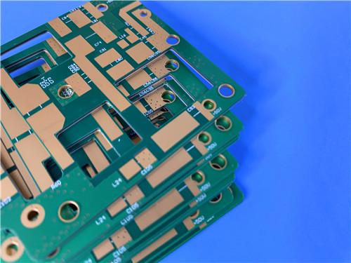
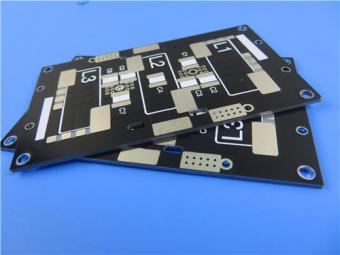
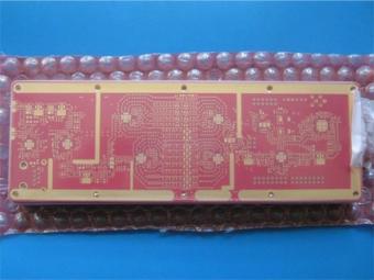
This 4-layer RT/duroid 5880 High Tg FR-4 Hybrid PCB represents a balance of RF performance and structural practicality.
Item NO.:
BIC-554-v639.0Order(MOQ):
1-10Payment:
T/TProduct Origin:
ChinaShipping Port:
ShenzhenLead Time:
7-10 days
4-layer RT/duroid 5880+TG175 FR4 Hybrid PCB with ENIG Controlled Depth Slots
Product overview
This 4-layer hybrid circuit board is engineered for high-frequency RF/microwave applications requiring exceptional electrical performance, mechanical stability, and reliable manufacturability. By combining Rogers RT/duroid 5880 — a premium glass microfiber-reinforced PTFE composite—with high-Tg 175 FR-4 material, this mixed dielectric material PCB delivers low insertion loss, stable dielectric properties, and robust thermal performance in a compact 90mm x80mm form factor. Built to IPC Class 3 standards for high-reliability electronics, it supports demanding use cases including aerospace communication systems, radar front-ends, millimeter-wave modules, and broadband wireless equipment.
The hybrid stack-up optimizes cost and performance:RTduroid 5880 serves as the low-loss high-frequency core, while high-Tg FR-4 provides structural rigidity, thermal resistance, and compatibility with standard PCB assembly processes. With immersion gold surface finish, controlled depth slots, and tight dimensional control, this board balances electrical purity, mechanical precision, and long-term operational stability in harsh environmental conditions.

PCB Construction Details
This section summarizes the physical and structural specifications defining the board’s build, materials, and quality level.
|
Parameter |
Specification |
|
Base Material |
RT/duroid 5880 + High Tg FR-4 |
|
Layer Count |
4 Layers |
|
Board Dimensions |
90mm × 80mm (1 PCB per panel) |
|
Finished Board Thickness |
1.0 mm |
|
Finished Cu Weight (Outer Layers) |
1 oz (≈ 35 µm) |
|
Finished Cu Weight (Inner Layers) |
0.5 oz (≈ 18 µm) |
|
Via Plating Thickness |
25 µm |
|
Surface Finish |
Immersion Gold (ENIG), 2 µinch gold thickness |
|
Solder Mask |
Blue |
|
Silkscreen |
White |
|
Controlled Depth Slots |
Yes (integrated) |
|
Hole Copper Thickness |
25 µm |
|
Minimum Trace/Space |
4/4 mils (design dependent) |
|
Minimum Hole Size |
0.25 mm (design dependent) |
|
Acceptance Criteria |
IPC Class 3 |
|
Electrical Test |
100% Electrical Test |
PCB Stack-Up
This table defines the layer sequence, dielectric materials, thicknesses, and copper distribution across the full 4-layer PCB stack-up.

Typical Applications
This hybrid 4-layer PCB is ideal for applications requiring both high-frequency performance and structural robustness:
Key Design & Functional Features
1) Hybrid Material Architecture
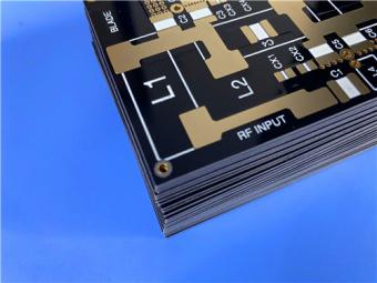
The board uses a dual-material strategy to separate high-frequency signal paths from digital/control circuits.Rogers 5880 forms the outer signal/reference layers to preserve microwave performance with stable dielectric constant (Dk≈2.20) and ultra-low dissipation factor (Df≈0.0004 at 10 GHz). High-Tg 175 FR-4 occupies the inner layers to provide mechanical strength, heat resistance, and cost efficiency. This split ensures low insertion loss, consistent impedance control, and immunity to signal distortion at frequencies up to Ku-band and beyond.
2) Impedance & High-Frequency Performance
With tightly controlled dielectric thickness and copper distribution, the board supports 50Ωsingle-ended and 100Ωdifferential impedance for microstrip and stripline topologies. The isotropic electrical properties of RT/duroid 5880 ensure consistent performance across the panel and over wide frequency ranges, minimizing phase shift and signal skew. Low moisture absorption (< 0.02%) maintains stable electrical characteristics even in high-humidity environments.
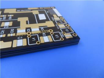
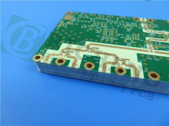
3) Controlled Depth Slots
Controlled depth slots are precision-machined features that extend only partway through the board thickness, not fully penetrating the laminate. They are used for mechanical isolation, component mounting, thermal management, or structural segmentation. Fabricated using controlled routing parameters to avoid delamination or burrs, these slots preserve board rigidity while enabling modular design and heat dissipation in compact RF assemblies.
4) Plating & Surface Finish
Immersion gold (2μinch) provides a flat, oxidation-resistant surface for consistent soldering, wire bonding, and contact reliability. Via and through-hole plating thickness is maintained at 25μm to ensure current-carrying capacity, thermal cycling resistance, and long-term conductivity. The combination of hard gold surface and uniform plating meets the structural and electrical demands of aerospace, defense, and high-end communication hardware.
5) IPC Class 3 Compliance
Built to IPC Class 3 standards, the board is validated for applications requiring continuous operation without failure. It undergoes rigorous testing for peel strength, hole quality, registration, solder mask adhesion, and thermal cycle resistance. This certification makes it suitable for mission-critical systems in aerospace, military radar, satellite communications, and industrial control.
6) Mechanical & Thermal Performance
The 1.0 mm overall thickness balances rigidity and compactness. High-Tg FR-4 (175°C) prevents thermal decomposition during lead-free reflow and continuous high-temperature operation. The hybrid stack-up reduces warpage and ensures dimensional stability under thermal stress. RT/duroid 5880’s low coefficient of thermal expansion (CTE) minimizes stress on vias and components during temperature cycling.
RT/duroid 5880 Copper Clad Laminate (CCL) Technical Overview
Introduction to RT/duroid 5880
RT/duroid 5880 is a glass microfiber reinforced Polytetrafluoroethylene (PTFE) composite. It is the industry benchmark forhigh-frequency circuit laminateswhere wide bandwidth, low signal loss, and high phase stability are paramount. Unlike standard PTFE, the random orientation of the glass microfibers eliminates anisotropic dielectric constant variations, ensuring consistent impedance performance across the entire panel.
Why choose RT/duroid 5880 for your hybrid design?
1)Exceptional Low Loss: The dissipation factor of 0.0009 at 10 GHz allows high-power amplifiers to run cooler and receivers to achieve lower noise figures.
2)Uniform Dk: The dielectric constant of 2.20±0.02 ensures tight impedance control (typically±5% tolerance on 50Ωlines).
3)Moisture Resistance: At 0.02% moisture absorption, the electrical properties remain stable in humid environments (unlike standard FR-4 which shifts Dk significantly).
4)Machinability: Despite being soft, it can be sheared, punched, and routed, making it suitable for complex cavity and step-structure designs.
RT/duroid 5880 Complete Technical Data Sheet
|
PROPERTY |
RT/duroid® 5880 |
Direction |
Units |
Condition |
Test Method |
|
Dielectric Constant, εr (Process spec.) |
2.20 ± 0.02 |
Z |
— |
10 GHz / 23°C |
IPC-TM-650 2.5.5.5 |
|
Dielectric Constant, εr (Design value) |
2.2 |
Z |
— |
8–40 GHz |
Differential Phase Length Method |
|
Dissipation Factor, tan δ |
0.0004 @1MHz 0.0009 @10GHz |
Z |
— |
C24/23/50 |
IPC-TM-650 2.5.5.3 / 2.5.5.5 |
|
Thermal Coefficient of εr |
-125 |
Z |
ppm/°C |
-50 to 150°C |
IPC-TM-650 2.5.5.5 |
|
Volume Resistivity |
2 × 10⁷ |
Z |
MΩ·cm |
C96/35/90 |
ASTM D257 |
|
Surface Resistivity |
3 × 10⁷ |
Z |
MΩ |
C96/35/90 |
ASTM D257 |
|
Specific Heat |
0.96 (0.23) |
— |
J/g/K (cal/g/°C) |
— |
Calculated |
|
Tensile Modulus @23°C |
1070 (156) / 860 (125) |
X / Y |
MPa (kpsi) |
RT |
ASTM D638 |
|
Tensile Modulus @100°C |
450 (65) / 380 (55) |
X / Y |
MPa (kpsi) |
100°C |
ASTM D638 |
|
Tensile Strength @23°C |
29 (4.2) / 27 (3.9) |
X / Y |
MPa (kpsi) |
RT |
ASTM D638 |
|
Tensile Strength @100°C |
20 (2.9) / 18 (2.6) |
X / Y |
MPa (kpsi) |
100°C |
ASTM D638 |
|
Tensile Strain (%) @23°C |
6.0 / 4.9 |
X / Y |
% |
RT |
ASTM D638 |
|
Tensile Strain (%) @100°C |
7.2 / 5.8 |
X / Y |
% |
100°C |
ASTM D638 |
|
Compressive Modulus @23°C (X/Y/Z) |
710 (103) / 710 (103) / 940 (136) |
X / Y / Z |
MPa (kpsi) |
RT |
ASTM D695 |
|
Compressive Modulus @100°C (X/Y/Z) |
500 (73) / 500 (73) / 670 (97) |
X / Y / Z |
MPa (kpsi) |
100°C |
ASTM D695 |
|
Compressive Strength @23°C (X/Y/Z) |
27 (3.9) / 29 (5.3) / 52 (7.5) |
X / Y / Z |
MPa (kpsi) |
RT |
ASTM D695 |
|
Compressive Strength @100°C (X/Y/Z) |
22 (3.2) / 21 (3.1) / 43 (6.3) |
X / Y / Z |
MPa (kpsi) |
100°C |
ASTM D695 |
|
Compressive Strain (%) @23°C (X/Y/Z) |
8.5 / 7.7 / 12.5 |
X / Y / Z |
% |
RT |
ASTM D695 |
|
Compressive Strain (%) @100°C (X/Y/Z) |
8.4 / 7.8 / 17.6 |
X / Y / Z |
% |
100°C |
ASTM D695 |
|
Moisture Absorption |
0.02 |
— |
% |
D48/50 (0.062″ thickness) |
ASTM D570 |
|
Thermal Conductivity |
0.2 |
Z |
W/m/K |
80°C |
ASTM C518 |
|
Coefficient of Thermal Expansion (X) |
31 |
X |
ppm/°C |
0–100°C |
IPC-TM-650 2.4.41 |
|
Coefficient of Thermal Expansion (Y) |
48 |
Y |
ppm/°C |
0–100°C |
IPC-TM-650 2.4.41 |
|
Coefficient of Thermal Expansion (Z) |
237 |
Z |
ppm/°C |
0–100°C |
IPC-TM-650 2.4.41 |
|
Thermal Decomposition Temperature (Td) |
500 |
— |
°C TGA |
— |
ASTM D3850 |
|
Density |
2.2 |
— |
g/cm³ |
— |
ASTM D792 |
|
Copper Peel Strength (1 oz ED Foil) |
31.2 (5.5) |
— |
pli (N/mm) |
After solder float |
IPC-TM-650 2.4.8 |
|
Flammability Rating |
V-0 |
— |
— |
— |
UL94 |
|
Lead-Free Process Compatible |
Yes |
— |
— |
— |
|
Standard Specifications
Typical Applications
Fabrication Notes
RT/duroid 5880 is softer than standard FR-4 and requires careful handling:
Conclusion
This 4-layer RT/duroid 5880 High Tg FR-4 Hybrid PCB represents a balance of RF performance and structural practicality. By isolating the high-frequency signal path entirely on the RT/duroid material and utilizing controlled depth slots, engineers can achieve RF performance approaching pure PTFE laminates while utilizing FR-4 for cost-sensitive support layers. The IPC Class 3 qualification ensures this RT/Duroid 5880 Hybrid PCB is suitable for mission-critical and harsh environment deployment.


Previous:
8-Layer RO4350B Tg180 FR-4 Mixed Dielectric Material PCB Blind Buried Via ENIGNext:
4-layer RO4003C+TG175 FR4 Hybrid PCB 1.4mm Finished Board Thick ENIGIf you have questions or suggestions,please leave us a message,we will reply you as soon as we can!
Categories
New Products
Wangling 5mil 0.127mm TFA300 Core 2-layer Immersion Gold Green Solder Mask PCB
7.5mil AGC Taconic TLY-5 Substrate Custom PCB EPIG Finish Bare Copper
10mil Rogers CuClad 250 Immersion Gold 2-Layer Rigid Microwave PCB
20mil F4BTMS450 Wangling DK4.5 Laminate Custom PCB HASL LF Finsh
F4BME275 Wangling DK2.75 Laminate 2-Layer 1.6mm Pure Gold RF Custom PCB
Wangling F4BTD350S High Frequency PCB 2-layer 20mil Thick ENIG DK3.5 Substrate

12-layer TG200 TU-872 SLK High-Speed FR4 1.68mm PCB with ENIG Impedance Control

12-Layer RO4350B + RO3010 3.14mm Hybrid PCB Nickel-Free EPIG Surface Finish Blind Via
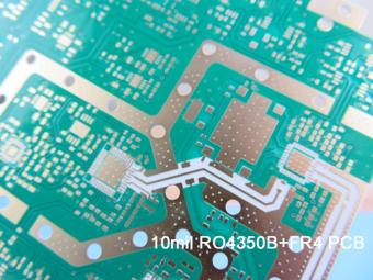
RO4003C exhibit a stable dielectric constant over a broad frequency range. This makes it an ideal substrate for broadband applications. And signal integrity performance improvement over the stack-ups with all FR4 board.
The hybrid PCB can be a mixture of FR-4 and high frequency material, and a mixture of high frequency material with different dielectric constant (DK)
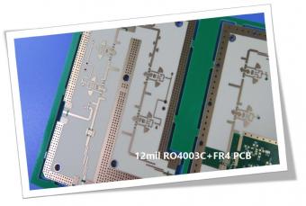
The 12mil core is on the top layer and it mainly plays the roles of signal layer. The core has fixed thickness which is very important to the electrical length of RF lines on the circuit board.
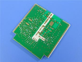
The hybrid PCB can be a mixture of FR-4 and high frequency material as abovementioned.
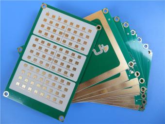
It contains 2 different boards in the panel. PCB boards are manufactured strictly as per required specifications with the standard IPC-Class-II.
Hybrid PCB is also known as mixed material lamination, it’s normally combined by two different material like FR4 and PI(rigid flex PCB), FR4 and Ceramic, FR4 and Teflon, FR4 and Aluminum base etc.
Hybrid constructions PCB typically involve a low loss material such as Nelco or Rogers combined with another core material like FR-4.
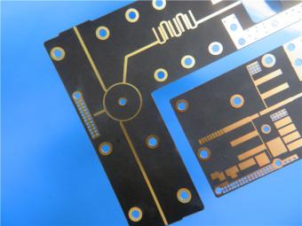
The Hybrid PCB on RO3003 and High Tg FR-4 is a state-of-the-art solution for high-frequency applications. With its exceptional stability, reliability, and manufacturability, it caters to the demands of industries such as automotive, telecommunications, and satellite communications.
 6-11C Shidai Jingyuan, Fuyong, Baoan, Shenzhen, Guangdong, China 518103


For inquiries about our products or pricelist, please leave to us and we will be in touch within 24 hours.
© Copyright: 2026 Shenzhen Bicheng Electronics Technology Co., Ltd.. All Rights Reserved.

IPv6 network supported


