

 Call Us Now !
Tel : +86 755 27374946
Call Us Now !
Tel : +86 755 27374946
 Order Online Now !
Email : info@bichengpcb.com
Order Online Now !
Email : info@bichengpcb.com
The RT/duroid 5870 laminate is the material of choice for engineers who require consistent, predictable, and ultra-low-loss performance from DC to millimeter-wave frequencies.
Item NO.:
BIC-549-v634.0Order(MOQ):
1-10Payment:
T/TProduct Origin:
ChinaShipping Port:
ShenzhenLead Time:
7-10 days
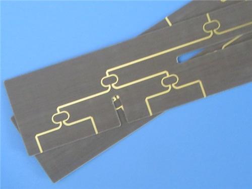
Rogers RT/duroid 5870 PCB 2-layer 10mil Laminate ENIG Finish Bare Copper
Introduction
This is engineering-grade product description for a2-layer rigid high-frequency PCB built on Rogers RT/duroid 5870 dielectric with a nominal core thickness of 10 mil (0.254 mm). Targeted at RF/microwave engineers, aerospace system designers, and high-reliability electronics manufacturers, this description emphasizes electrical performance, mechanical stability, fabrication control, quality assurance, and field reliability. All specifications comply with IPC-Class2 standards and are validated by full electrical testing before shipment.
1. Overview & Positioning
This RT/duroid 5870 PCB is a precision-engineered high-frequency substrate solution optimized for microwave, millimeter-wave, and Ku-band applications where low insertion loss, stable dielectric properties, and consistent impedance control are mission-critical. Unlike standard FR-4 or general-purpose high-speed laminates, RT duroid 5870 is a glass-microfiber-reinforced PTFE composite formulated to deliver exceptional electrical uniformity across wide frequency ranges, minimal signal attenuation, and strong environmental robustness. The 10-mil thin-core construction supports compact, lightweight designs while maintaining mechanical integrity for automated assembly and field operation. This board is ideal for aerospace antennas, radar front-ends, point-to-point radio links, guidance systems, and high-performance microstrip/stripline circuits.
2. PCB Construction Details
This section summarizes the complete physical build, surface finishing, and fabrication constraints of the board, ensuring compatibility with high-frequency assembly and test flows.
|
Parameter |
Specification |
|
Base Material |
RT/duroid® 5870 (Rogers) |
|
Layer Count |
2 layers |
|
Board Dimensions |
85 mm × 36 mm per panel, ±0.15 mm |
|
Minimum Trace / Space |
5 / 6 mils (approx. 0.127 mm / 0.152 mm) |
|
Minimum Hole Size |
0.4 mm |
|
Blind Vias |
None |
|
Finished Board Thickness |
0.3 mm (10 mil) |
|
Finished Copper Weight (outer) |
1 oz (35 μm) |
|
Via Plating Thickness |
20 μm |
|
Surface Finish |
Electroless Nickel Immersion Gold (ENIG) |
|
Top / Bottom Silkscreen |
No |
|
Top / Bottom Solder Mask |
No |
|
Electrical Test |
100% prior to shipment |
3. PCB Stackup Structure
The stackup defines the layer sequence and thickness balance, directly controlling impedance, loss, and thermal behavior in high-frequency transmission lines.
|
Layer |
Material |
Thickness |
|
Copper Layer 1 (Top) |
Copper (1 oz) |
35 μm (1.4 mil) |
|
Dielectric Core |
RT/duroid® 5870 |
0.254 mm (10 mil) |
|
Copper Layer 2 (Bottom) |
Copper (1 oz) |
35 μm (1.4 mil) |
4. PCB Layout & Net Statistics
These metrics reflect routing complexity, component density, and interconnect structure for assembly and simulation modeling.
|
Parameter |
Count |
|
Components |
36 |
|
Total Pads |
56 |
|
Thru hole Pads |
32 |
|
Top SMT Pads |
24 |
|
Bottom SMT Pads |
0 |
|
Vias |
28 |
|
Nets |
2 |

5. Core Performance Advantages
5.1 Electrical Superiority
Rogers 5870 provides Dk = 2.33±0.02 @ 10 GHz with extremely tight lot-to-lot consistency, enabling accurate impedance prediction and simulation matching. The dissipation factor is 0.0012 @ 10 GHz, one of the lowest among reinforced PTFE materials, drastically reducing insertion loss in long traces, antenna feeds, and filter structures. Stable electrical performance extends reliably into Ku-band and millimeter-wave regions, supporting modern broadband communication and sensing systems.
5.2 Mechanical & Thermal Stability
The laminate exhibits isotropic electrical behavior, meaning consistent performance in X, Y, and Z directions, reducing signal skew and improving impedance uniformity. Coefficients of thermal expansion (CTE) are well-balanced: X-axis 22 ppm/°C, Y-axis 28 ppm/°C, Z-axis 173 ppm/°C. This matches copper and component packaging closely, lowering thermomechanical stress during thermal cycling and enhancing long-term solder joint reliability.
5.3 Environmental Resistance
Moisture absorption is only 0.02%, making the material exceptionally stable in high-humidity outdoor, airborne, or shipboard environments. Unlike many hydrocarbon-based substrates, RT/duroid 5870 resists degradation, drift, and leakage caused by moisture ingress. It is chemically inert against common PCB etchants, plating solutions, solvents, and reagents used in fabrication, ensuring consistent yield and performance across production runsRogers Corporation.
5.4 Fabrication & Assembly Compatibility
Despite being a PTFE-based high-performance material,RT/duroid 5870 substratemachines, drills, routes, and cuts cleanly. Plated through-holes are robust with 20μm via plating, supporting reliable interlayer connection. The ENIG surface finish provides excellent solderability, fine-pitch contact stability, and corrosion resistance—critical for aerospace and defense applications. The absence of solder mask and silkscreen preserves high-frequency performance by eliminating parasitic losses and geometry variationsRogers Corporation.
6. Typical Target Applications
This 10-mil RT/duroid 5870 PCB is purpose-built for:
Deep Dive: RT/duroid 5870 Copper Clad Laminate (CCL) Knowledge
This section is fully separated from the PCB assembly description and provides detailed CCL material science, specifications, comparison, and application guidance for engineering selection and design validation.
1. Basic Introduction to RT/duroid 5870 CCL
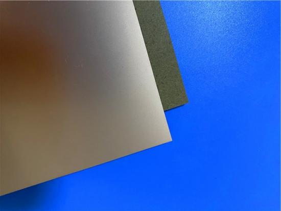
Rogers RT/duroid 5870 is a high-frequency glass-microfiber-reinforced PTFE copper clad laminate designed for demanding RF, microwave, and millimeter-wave circuits. The random orientation of microfibers creates exceptional dielectric constant uniformity panel-to-panel and across frequency. It is widely recognized as a benchmark material for low loss, stable Dk, and mechanical ruggedness in professional high-frequency systems.
2.RT/duroid 5870 Datasheet Values
|
Property |
Direction |
Value |
Unit |
Condition |
Test Method |
|
Dielectric Constant, εr (process spec) |
Z |
2.33 ±0.02 |
– |
10 GHz, 23°C |
IPC-TM-650 2.5.5.5 |
|
Dielectric Constant, εr (design) |
Z |
2.33 |
– |
8–40 GHz |
Differential Phase Length Method |
|
Dissipation Factor, tan δ |
Z |
0.0012 |
– |
10 GHz, 23°C |
IPC-TM-650 2.5.5.5 |
|
Dissipation Factor, tan δ |
Z |
0.0005 |
– |
1 MHz |
IPC-TM-650 2.5.5.3 |
|
TCDk |
Z |
-115 |
ppm/°C |
-50 to 150°C |
IPC-TM-650 2.5.5.5 |
|
Volume Resistivity |
Z |
2 × 10⁷ |
MΩ·cm |
C96/35/90 |
ASTM D257 |
|
Surface Resistivity |
Z |
2 × 10⁷ |
MΩ |
C96/35/90 |
ASTM D257 |
|
Specific Heat |
N/A |
0.96 (0.23) |
J/g/K (cal/g/°C) |
– |
Calculated |
|
Tensile Modulus (23°C) |
X |
1300 (189) |
MPa (kpsi) |
23°C |
ASTM D638 |
|
Tensile Modulus (23°C) |
Y |
1280 (185) |
MPa (kpsi) |
23°C |
ASTM D638 |
|
Tensile Modulus (100°C) |
X |
490 (71) |
MPa (kpsi) |
100°C |
ASTM D638 |
|
Tensile Modulus (100°C) |
Y |
430 (63) |
MPa (kpsi) |
100°C |
ASTM D638 |
|
Ultimate Tensile Stress (23°C) |
X |
50 (7.3) |
MPa (kpsi) |
23°C |
ASTM D638 |
|
Ultimate Tensile Stress (23°C) |
Y |
42 (6.1) |
MPa (kpsi) |
23°C |
ASTM D638 |
|
Ultimate Tensile Strain |
X / Y |
9.8 / 9.8 |
% |
23°C |
ASTM D638 |
|
Compressive Modulus (23°C) |
X |
1210 (176) |
MPa (kpsi) |
23°C |
ASTM D695 |
|
Compressive Modulus (23°C) |
Y |
1360 (198) |
MPa (kpsi) |
23°C |
ASTM D695 |
|
Compressive Modulus (23°C) |
Z |
803 (120) |
MPa (kpsi) |
23°C |
ASTM D695 |
|
Coefficient of Thermal Expansion (CTE) |
X |
22 |
ppm/°C |
0–100°C |
IPC-TM-650 2.4.41 |
|
CTE |
Y |
28 |
ppm/°C |
0–100°C |
IPC-TM-650 2.4.41 |
|
CTE |
Z |
173 |
ppm/°C |
0–100°C |
IPC-TM-650 2.4.41 |
|
Thermal Conductivity |
Z |
0.22 |
W/m/K |
80°C |
ASTM C518 |
|
Decomposition Temperature (Td) |
N/A |
500 |
°C (TGA) |
– |
ASTM D3850 |
|
Density |
N/A |
2.2 |
g/cm³ |
23°C |
ASTM D792 |
|
Copper Peel Strength |
N/A |
27.2 (4.8) |
N/mm (pli) |
After solder float, 1 oz. EDC foil |
IPC-TM-650 2.4.8 |
|
Moisture Absorption |
N/A |
0.02 |
% |
0.062" (1.6mm), D48/50 |
ASTM D570 |
|
Flammability |
N/A |
V-0 |
– |
– |
UL94 |
3. Material Structure & Advantages
3.1 PTFE + Random Glass Microfibers
PTFE provides inherently low loss and chemical inertness. Random microfibers boost mechanical strength, dimensional stability, and machinability while preserving electrical isotropy—avoiding Dk variation between warp and weft directions seen in woven glass substrates.
3.2 Ultra-Low Loss
Among reinforced PTFE laminates, RT/duroid 5870 offers the lowest electrical loss, making it superior to many competing materials for long-reach RF links, high-Q filters, and antenna arrays where efficiency directly impacts link budget and noise performanceRogers Corporation.
3.3 Excellent Chemical Resistance
Stable against acids, alkalis, solvents, and plating chemistries used in PCB manufacturing. This ensures consistent plating adhesion, via reliability, and yield without degradation of electrical propertiesRogers Corporation.
3.4 Low Moisture Sensitivity
Near-zero moisture uptake prevents Dk/Df drift in humid environments, a common failure mode in airborne, marine, and outdoor basestation equipment.

4. Why Choose RT/duroid 5870 CCL?
5. Standard Configurations & Availability
RT/duroid 5870 material is commercially available in a wide range of thicknesses and panel sizes. For this specific design (0.010" or 0.254mm), the manufacturing tolerances are tightly controlled.
|
Parameter |
Options / Specifications |
|
Standard Thicknesses |
0.005" (0.127mm), 0.010" (0.254mm) , 0.020" (0.508mm), 0.031" (0.787mm), 0.062" (1.575mm) |
|
Standard Panel Sizes |
18"x12" (457x305mm), 18"x24" (457x610mm) |
|
Standard Claddings |
Electrodeposited (ED) Copper: ½ oz (18µm), 1 oz (35µm), 2 oz (70µm) |
|
Advanced Claddings |
Rolled Copper Foil (for lowest loss), Aluminum, Brass, Resistive Foil |
|
Copper Treatment |
HH/HH (ED), H1/H1 (Reverse Treated), 1R/1R (Rolled Annealed) |
Conclusion
The RT/duroid 5870 laminate is the material of choice for engineers who require consistent, predictable, and ultra-low-loss performance from DC to millimeter-wave frequencies. Our PCB built on0.010” (0.254 mm) RT/duroid 5870 core leverages all these advantages, offering a ready-to-use solution for prototype or production runs. For further technical support or custom stackups, please contact our application engineering team.


Previous:
Rogers CLTE-MW PCB 2.9mil 2-layer Immersion Gold No Solder Mask Black SilkscreenNext:
150mil Rogers TMM13i 2-layer ENIG Bare Copper Custom PCBIf you have questions or suggestions,please leave us a message,we will reply you as soon as we can!
Categories
New Products

12-layer TG200 TU-872 SLK High-Speed FR4 1.68mm PCB with ENIG Impedance Control

12-Layer RO4350B + RO3010 3.14mm Hybrid PCB Nickel-Free EPIG Surface Finish Blind Via
8-Layer Hybrid PCB RO4003C + S1000-2M FR4 with ENIG Surface Finish Blind Via
6-Layer Isola Astra MT77 PCB with Blind Via & Resin Plug Immersion Silver Finish

2-Layer 20mil FSD1020T ENIG High-Frequency PCB with Via Resin Plugged and Capped

4-Layer F4BM265+S1000-2M Material Hyrbid PCB with Blind Via Impedance Control & ENIG

4-Layer Wangling WL-CT338 + FR4 Hybrid PCB ENIG Green Solder Mask White Silkscreen

6-layer Isola 370HR High-Tg FR-4 PCB 2μ" ENIG Impedance Controlled
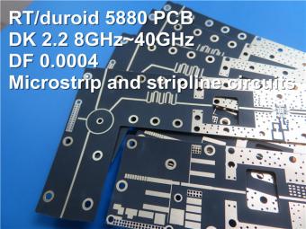
This is a type of double sided RF PCB built on RT/duroid 5880 for the application of Radar Systems.
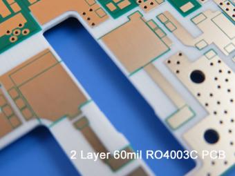
RO4003C PCBs are hydrocarbon ceramic filled laminates, not PTFE which are designed to offer superior high frequency performance.
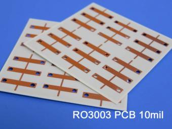
Rogers RO3003 high frequency circuit materials are ceramic-filled PTFE composites intended for use in commercial microwave and RF applications. It was designed to offer exceptional electrical and mechanical stability at competitive prices.
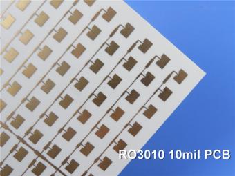
RO3010 laminates are competitively priced products with exceptional mechanical and electrical stability. This stability simplifies the design of broadband components and allows the materials to be used in a wide range of applications over a very broad range of frequencies.
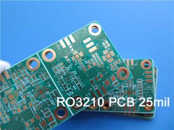
These RO3210 materials are engineered to offer exceptional electrical performance and mechanical stability. RO3210 laminates combine the surface smoothness of a non-woven PTFE laminate.
RT/duroid 6035HTC laminates are an exceptional choice for high power applications.
TC350 is designed to provide enhanced heat-transfer through “Best-In-Class” thermal conductivity, while reducing dielectric loss and insertion loss. Lower losses result in higher Amplifier and Antenna Gains/Efficiencies.
RO3035 materials exhibit a coefficient of thermal expansion(CTE) in the X and Y axis of 17 ppm/℃. This expansion coefficient is matched to that of copper, which allows the material to exhibit excellent dimensional stability.
 6-11C Shidai Jingyuan, Fuyong, Baoan, Shenzhen, Guangdong, China 518103


For inquiries about our products or pricelist, please leave to us and we will be in touch within 24 hours.
© Copyright: 2026 Shenzhen Bicheng Electronics Technology Co., Ltd.. All Rights Reserved.

IPv6 network supported


