

 Call Us Now !
Tel : +86 755 27374946
Call Us Now !
Tel : +86 755 27374946
 Order Online Now !
Email : info@bichengpcb.com
Order Online Now !
Email : info@bichengpcb.com
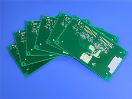
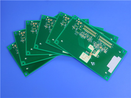
This 8-layer RO4003C & S1000-2M hybrid PCB achieves a balanced solution between high-frequency electrical performance, multi-layer structural reliability and manufacturing cost, solving the core pain points of single-material PCBs in RF communication hardware.
Item NO.:
BIC-589-v674.0Order(MOQ):
1-10Payment:
T/TProduct Origin:
ChinaShipping Port:
ShenzhenLead Time:
7-10 days
8-Layer Hybrid PCB RO4003C + S1000-2M FR4 with ENIG Surface Finish Blind Via
Product Brief Introduction
This custom 8-layer hybrid laminate PCB integrates Rogers RO4003C high-frequency hydrocarbon ceramic substrates and Shengyi S1000-2M high-Tg low Z-CTE FR4 prepreg, targeting RF microwave, automotive radar, and base station communication hardware that simultaneously demands ultra-low high-frequency signal loss and reliable multi-layer mechanical structure.
Traditional full Rogers multi-layer PCBs suffer from high raw material cost and complicated lamination yield control; pure FR4 boards cannot meet low insertion loss requirements above 500MHz. This hybrid stacking architecture balances high-frequency electrical performance, manufacturing cost and thermal-mechanical reliability, forming a differentiated competitive advantage compared with single-material PCB solutions. The mixed copper inner layer design optimizes power plane current carrying capacity and high-speed signal routing density, while blind vias and resin plug technology eliminate cavity risks during reflow soldering and enhance high-density layout feasibility.
1. PCB Construction Details
The following table summarizes the complete construction parameters, highlighting the strategic material placement and layer sequencing that enables optimal signal integrity and thermal management.
|
Parameter |
Specification |
|
Base Material |
RO4003C + S1000-2M (Hybrid Construction) |
|
Layer Count |
8 Layers |
|
Board Dimensions |
273mm x 185mm (Including process edge) |
|
Finished Board Thickness |
1.6mm ± tolerance |
|
Finished Copper Weight (Outer Layers) |
1 oz (35μm) |
|
Finished Copper Weight (Inner Layers) |
0.5 oz / 1 oz mixed configuration |
|
Surface Finish |
Immersion Gold (ENIG) |
|
Top Silkscreen |
White Legend |
|
Bottom Silkscreen |
White Legend |
|
Top Solder Mask |
Green Solder Mask |
|
Bottom Solder Mask |
Green Solder Mask |
|
Electrical Testing |
100% Electrical Test prior to shipment |
|
Blind Vias |
L1-L2, L7-L8 |
|
Resin Plug Vias |
0.2mm, 0.25mm, 0.35mm |
2. PCB Stackup Configuration
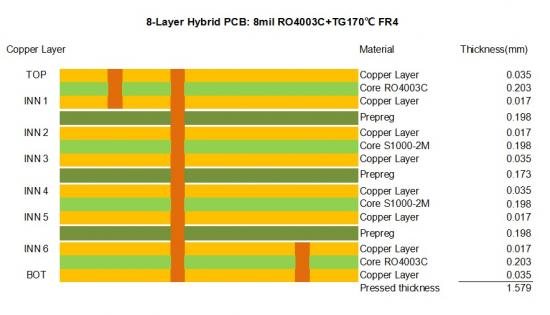
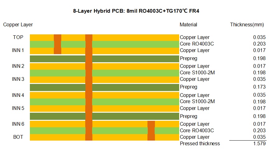
The layer stackup is engineered with symmetrical construction to minimize warpage during thermal cycling, with high-frequency RO4003C cores placed on outer positions to optimize signal launch and termination performance.
3. Core Differentiated Technical Advantages of This Hybrid PCB
3.1 Dual High-Frequency Outer Layer Design:
3.2 S1000-2M Middle Dielectric Stabilizes Multi-Layer Reliability:
3.3 Optimized Interconnection Process Matching:
4. Application Scenarios
This 8-layer hybrid PCB is specifically tailored for applications requiring a combination of high-frequency signal processing and robust power delivery within a single integrated substrate. Typical applications include:
5. PCB Section Conclusion
This 8-layer RO4003C & S1000-2M hybrid PCB achieves a balanced solution between high-frequency electrical performance, multi-layer structural reliability and manufacturing cost, solving the core pain points of single-material PCBs in RF communication hardware. The standardized stackup, controlled blind/resin plug via process and unified surface treatment parameters ensure stable batch production consistency. It is universally applicable to cellular base station power amplifiers, automotive millimeter-wave radar, satellite LNB modules and broadband RF identification equipment, with scalable customization on panel size, copper weight and hole dimension based on client design requirements.
CCL Material Knowledge: RO4003C and S1000-2M
1. Rogers RO4003C High-Frequency Laminate
1.1 Material Overview
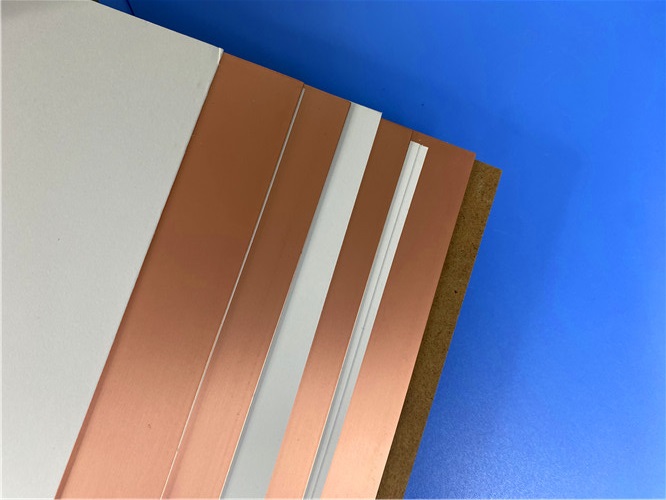
Rogers 4003C is a hydrocarbon ceramic laminate developed by Rogers Corporation specifically for high-frequency circuit applications. Unlike PTFE-based materials that require specialized processing, RO4003C is a rigid thermoset material that can be fabricated using standard FR-4 processing techniques. This characteristic significantly reduces manufacturing complexity and cost while delivering superior high-frequency performance. The hydrocarbon ceramic filler system provides a unique combination of low dielectric loss, stable dielectric constant over temperature and frequency, and excellent dimensional stability.
1.2 Rogers RO4003C High-Frequency CCL Full Datasheet Parameter Table
|
Property |
Typical Value |
Direction |
Units |
Condition |
Test Method |
|
Dielectric Constant, εr Process |
3.38 ± 0.05 |
Z |
— |
10 GHz/23°C |
IPC-TM-650 2.5.5.5 Clamped Stripline |
|
Dielectric Constant, εr Design |
3.55 |
Z |
— |
8-40 GHz |
Differential Phase Length Method |
|
Dissipation Factor, tan δ |
0.0027 |
Z |
— |
10 GHz/23°C |
IPC-TM-650 2.5.5.5 |
|
Dissipation Factor, tan δ |
0.0021 |
Z |
— |
2.5 GHz/23°C |
IPC-TM-650 2.5.5.5 |
|
Thermal Coefficient of εr |
40 |
Z |
ppm/°C |
-50°C to 150°C |
IPC-TM-650 2.5.5.5 |
|
Volume Resistivity |
1.7 × 10¹⁰ |
— |
MΩ·cm |
COND A |
IPC-TM-650 2.5.17.1 |
|
Surface Resistivity |
4.2 × 10⁹ |
— |
MΩ |
COND A |
IPC-TM-650 2.5.17.1 |
|
Electrical Strength |
31.2 (780) |
Z |
KV/mm (V/mil) |
0.51mm (0.020") |
IPC-TM-650 2.5.6.2 |
|
Tensile Modulus |
19,650 (2,850) |
X |
MPa (ksi) |
RT |
ASTM D638 |
|
Tensile Modulus |
19,450 (2,821) |
Y |
MPa (ksi) |
RT |
ASTM D638 |
|
Tensile Strength |
139 (20.2) |
X |
MPa (ksi) |
RT |
ASTM D638 |
|
Tensile Strength |
100 (14.5) |
Y |
MPa (ksi) |
RT |
ASTM D638 |
|
Flexural Strength |
276 (40) |
— |
MPa (kpsi) |
— |
IPC-TM-650 2.4.4 |
|
Dimensional Stability |
<0.3 |
X,Y |
mm/m (mils/inch) |
after etch +E2/150°C |
IPC-TM-650 2.4.39A |
|
CTE |
11 |
X |
ppm/°C |
-55 to 288°C |
IPC-TM-650 2.4.41 |
|
CTE |
14 |
Y |
ppm/°C |
-55 to 288°C |
IPC-TM-650 2.4.41 |
|
CTE |
46 |
Z |
ppm/°C |
-55 to 288°C |
IPC-TM-650 2.4.41 |
|
Tg |
>280 |
— |
°C TMA |
— |
IPC-TM-650 2.4.24.3 |
|
Td |
425 |
— |
°C TGA |
— |
ASTM D3850 |
|
Thermal Conductivity |
0.71 |
— |
W/m/°K |
80°C |
ASTM C518 |
|
Moisture Absorption |
0.06 |
— |
% |
48 hrs immersion, 50°C |
ASTM D570 |
|
Density |
1.79 |
— |
g/cm³ |
23°C |
ASTM D792 |
|
Copper Peel Strength |
1.05 (6.0) |
— |
N/mm (pli) |
after solder float |
IPC-TM-650 2.4.8 |
|
Flammability |
N/A |
— |
— |
— |
UL 94 |
|
Lead-Free Process Compatible |
Yes |
— |
— |
— |
— |
1.3 Key Advantages and Differentiators
1) Superior High-Frequency Performance:
2) FR-4 Process Compatibility:
3) Excellent Dimensional Stability:
4) High Thermal Reliability:
5) LoPro® Foil Option:
1.4 Design Considerations
1.5 Available Configurations
RO4003C is offered in standard thicknesses including:
2. Shengyi S1000-2M High-Performance FR4 Laminate
2.1 Material Overview
S1000-2M is a high-performance FR4 laminate manufactured by Shengyi Technology, designed for applications requiring superior thermal reliability and high layer count capability. The material features a high Tg of 185°C (DMA method), exceptional CAF (Conductive Anodic Filament) resistance, and demonstrated reliability through IST testing. S1000-2M is ideal for use in hybrid constructions with high-frequency materials, providing cost-effective support for power distribution, grounding, and lower-speed digital routing.
2.2 Shengyi S1000-2M High-Tg Low CTE FR4 Prepreg Datasheet Parameter Table
|
Property |
Condition |
Unit |
Specification |
Typical Value |
|
Tg |
DMA |
℃ |
≥180 |
185 |
|
Flammability |
C-48/23/50, E-24/125 |
Rating |
V-0 |
V-0 |
|
Volume Resistivity |
After moisture resistance |
MΩ·cm |
≥10⁶ |
6.79E+07 |
|
Volume Resistivity |
E-24/125 |
MΩ·cm |
≥10³ |
2.19E+08 |
|
Surface Resistivity |
After moisture resistance |
MΩ |
≥10⁴ |
3.16E+06 |
|
Surface Resistivity |
E-24/125 |
MΩ |
≥10³ |
2.24E+07 |
|
Arc Resistance |
D-48/50+D-0.5/23 |
S |
≥60 |
133 |
|
Dielectric Breakdown |
D-48/50+D-0.5/23 |
kV |
≥40 |
45kV+NB |
|
Dielectric Constant |
(1GHz) C-24/23/50 |
— |
— |
4.6 |
|
Dielectric Constant |
(1MHz) C-24/23/50 |
— |
≤5.4 |
4.9 |
|
Dissipation Factor |
(1GHz) C-24/23/50 |
— |
— |
0.018 |
|
Dissipation Factor |
(1MHz) C-24/23/50 |
— |
≤0.035 |
0.015 |
|
Thermal Stress |
288℃ solder dip |
— |
>10s, No Delamination |
>100s, No Delamination |
|
Peel Strength (1 oz) |
288℃/10s |
N/mm |
≥1.05 |
1.3 |
|
Flexural Strength |
LW |
MPa |
≥415 |
567 |
|
Flexural Strength |
CW |
MPa |
≥345 |
442 |
|
Water Absorption |
D-24/23 |
% |
≤0.5 |
0.08 |
|
CTE (Z-axis) |
Before Tg |
ppm/℃ |
≤60 |
41 |
|
CTE (Z-axis) |
After Tg |
ppm/℃ |
≤300 |
208 |
|
CTE (Z-axis) |
50-260℃ |
% |
≤3.0 |
2.4 |
|
Td |
5% weight loss |
℃ |
≥340 |
355 |
|
T260 |
TMA |
min |
≥30 |
60 |
|
T288 |
TMA |
min |
≥5 |
30 |
|
T300 |
TMA |
min |
≥2 |
15 |
|
CTI |
IEC60112 Method |
V |
PLC3(175-250) |
PLC3 (200V) |
2.3 Reliability Validation
1) High Layer Count Performance:
2) IST Testing:
3) CAF Resistance:
2.4 Prepreg Parameters
S1000-2M prepregs are offered in multiple glass fabric styles with controlled resin content and flow characteristics optimized for high layer count processing:
|
Designation |
Glass Fabric Type |
Performance |
Gel Time (sec) |
Resin Content (%) |
Resin Flow (%) |
Cured Thickness (µm) |
|
S1000-2M |
106 |
High Performance, Lower Z-axis CTE |
140±20 |
73±3 |
27±10 |
50 |
|
S1000-2M |
106 |
High Performance, Lower Z-axis CTE |
140±20 |
77±3 |
35±10 |
60 |
|
S1000-2M |
1080/1078 |
High Performance, Lower Z-axis CTE |
140±20 |
65±3 |
28±10 |
75 |
|
S1000-2M |
1080/1078 |
High Performance, Lower Z-axis CTE |
140±20 |
69±3 |
36±10 |
85 |
|
S1000-2M |
2313 |
High Performance, Lower Z-axis CTE |
140±20 |
57±3 |
25±10 |
100 |
|
S1000-2M |
2116 |
High Performance, Lower Z-axis CTE |
140±20 |
51±3 |
23±10 |
110 |
|
S1000-2M |
2116 |
High Performance, Lower Z-axis CTE |
140±20 |
57±3 |
29±10 |
125 |
|
S1000-2M |
1506 |
High Performance, Lower Z-axis CTE |
140±20 |
46±3 |
19±10 |
150 |
|
S1000-2M |
7628 |
High Performance, Lower Z-axis CTE |
140±20 |
49±3 |
24±10 |
200 |
2.5 Processing Recommendations
2.6 Hybrid Construction Synergies
The combination of RO4003C and S1000-2M in this 8-layer design leverages complementary properties:
CCL & Prepreg Material Chapter Conclusion
The matching combination of Rogers RO4003C high-frequency laminate and Shengyi S1000-2M low Z-CTE FR4 prepreg forms the core technical foundation of this 8-layer hybrid PCB. RO4003C supplies low-loss broadband high-frequency transmission capability for outer RF traces, while S1000-2M provides robust multi-layer thermal-mechanical bonding, humidity resistance and cost optimization.
All parameters cited in this chapter are fully extracted from official manufacturer datasheets with standardized IPC/ASTM test methods, providing accurate material performance reference for circuit design, impedance simulation, manufacturing process development and long-term product reliability assessment. The complementary material characteristics eliminate the respective limitations of single high-frequency substrate and ordinary FR4, which is the core differentiated advantage of hybrid RF PCBs compared with full Rogers or full FR4 alternatives.





Previous:
12-Layer RO4350B + RO3010 3.14mm Hybrid PCB Nickel-Free EPIG Surface Finish Blind ViaNext:
4-Layer F4BM265+S1000-2M Material Hyrbid PCB with Blind Via Impedance Control & ENIGIf you have questions or suggestions,please leave us a message,we will reply you as soon as we can!
Categories
New Products

Wangling F4BTMS220 2-Layer DK2.2 PCB 10 mil Core with Immersion Gold

Wangling F4BTME350 10mil DK3.5 High Frequency Substrate PCB 2-Layer Immersion Gold

Wangling F4BTM300 Custom 2-layer PCB 20mil DK3.0 Substrate with Immersion Gold

Rogers 20mil RT/duroid 6202 2-layer ENIG High-Frequency Microwave PCB

Rogers 20mil AD250C PCB Pure Gold High-Frequency Antenna Circuit Board

8-Layer Hybrid RF PCB: RO4350B + TG170 FR-4 + RO4003C with RO4450F Bondply

4-Layer Rogers RO3010 Hybrid PCB Immersion Silver 2.8mm Finished Thickness

4-Layer 20mil Rogers RO3210 ISIG High-Frequency PCB with Controlled Depth Milling
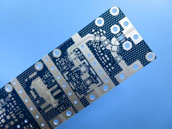
RO4003C exhibit a stable dielectric constant over a broad frequency range. This makes it an ideal substrate for broadband applications. And signal integrity performance improvement over the stack-ups with all FR4 board.
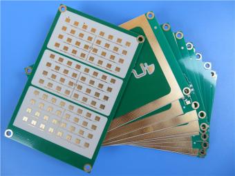
The hybrid PCB can be a mixture of FR-4 and high frequency material, and a mixture of high frequency material with different dielectric constant (DK)
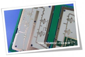
The 12mil core is on the top layer and it mainly plays the roles of signal layer. The core has fixed thickness which is very important to the electrical length of RF lines on the circuit board.
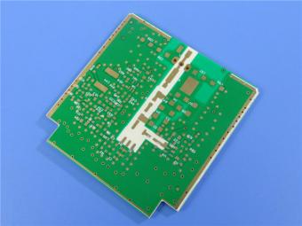
The hybrid PCB can be a mixture of FR-4 and high frequency material as abovementioned.
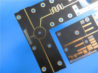
It contains 2 different boards in the panel. PCB boards are manufactured strictly as per required specifications with the standard IPC-Class-II.
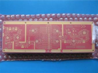
Hybrid PCB is also known as mixed material lamination, it’s normally combined by two different material like FR4 and PI(rigid flex PCB), FR4 and Ceramic, FR4 and Teflon, FR4 and Aluminum base etc.
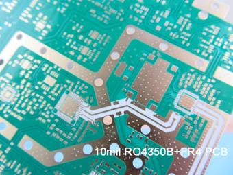
Hybrid constructions PCB typically involve a low loss material such as Nelco or Rogers combined with another core material like FR-4.
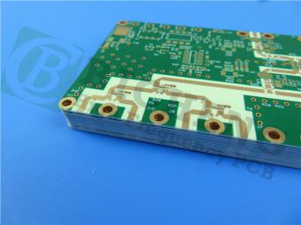
The Hybrid PCB on RO3003 and High Tg FR-4 is a state-of-the-art solution for high-frequency applications. With its exceptional stability, reliability, and manufacturability, it caters to the demands of industries such as automotive, telecommunications, and satellite communications.
 6-11C Shidai Jingyuan, Fuyong, Baoan, Shenzhen, Guangdong, China 518103


For inquiries about our products or pricelist, please leave to us and we will be in touch within 24 hours.
© Copyright: 2026 Shenzhen Bicheng Electronics Technology Co., Ltd.. All Rights Reserved.

IPv6 network supported


