

 Call Us Now !
Tel : +86 755 27374946
Call Us Now !
Tel : +86 755 27374946
 Order Online Now !
Email : info@bichengpcb.com
Order Online Now !
Email : info@bichengpcb.com
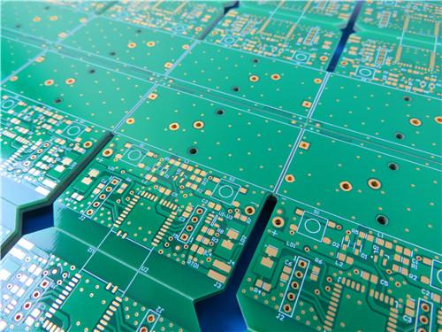
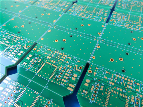
This 4-layer WL-CT338 + TG170 FR4 hybrid ENIG PCB forms a cost-performance balanced mixed-signal circuit substrate solution that addresses the core pain point of traditional single-material PCBs
Item NO.:
BIC-585-v670.0Order(MOQ):
1-10Payment:
T/TProduct Origin:
ChinaShipping Port:
ShenzhenLead Time:
7-10 days
4-Layer Wangling WL-CT338 + FR4 Hybrid PCB ENIG Green Solder Mask White Silkscreen
Product Overview
This 4-layer hybrid rigid PCB integrates domestic high-frequency hydrocarbon-ceramic CCL WL-CT338 and high-Tg 170℃ FR4 core materials, targeted for mixed-signal RF-digital integrated equipment including satellite communication modules, airborne radar front-end circuits, phase array antenna control boards, and microwave power amplifier substrates.
Different from full high-frequency laminates or pure FR4 PCBs, thishybrid stackup separates high-frequency RF signal routing layers and low-frequency power/ground digital layers via material zoning: Wangling WL-CT338 handles microwave transmission paths to minimize insertion loss and passive intermodulation (PIM), while TG170 FR4 undertakes power distribution, ground reference planes and digital logic circuits to control overall manufacturing cost without sacrificing high-frequency electrical performance.
The finished board adopts immersion gold (ENIG) surface finish, full green solder mask with double-sided white silkscreen, symmetrical copper weight design (1oz outer, 0.5oz inner), non-blind through-via architecture, and undergoes 100% continuity electrical testing before delivery. All fabrication processes strictly comply with IPC-6012 Class 2 aerospace-grade PCB manufacturing standards, with tightly controlled dimensional tolerance, thermal stability and impedance consistency for mass production consistency.
1. PCB Core Construction Details
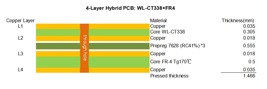
The board is manufactured as a 4-layer hybrid assembly integrating high-frequency WL-CT338 hydrocarbon ceramic material with standard FR-4 Tg170℃ substrate, delivering 1.47mm finished thickness with selective copper weighting optimized for signal integrity and power distribution.
|
Parameter |
Specification |
|
Base Material |
WL-CT338 + FR-4 Tg170℃ |
|
Layer Count |
4 Layers |
|
Board Dimensions |
175mm x 121mm (10 panels), tolerance ±0.15mm |
|
Finished Board Thickness |
1.47mm |
|
Outer Layer Copper Weight |
1 oz (0.035mm) Finished Cu |
|
Inner Layer Copper Weight |
0.5 oz (0.018mm) Finished Cu |
|
Blind/Buried Vias |
None |
|
Surface Finish |
Immersion Gold (ENIG) |
|
Top Silkscreen Color |
White |
|
Bottom Silkscreen Color |
White |
|
Top Solder Mask Color |
Green |
|
Bottom Solder Mask Color |
Green |
|
Electrical Testing |
100% Electrical Test Prior to Shipment |
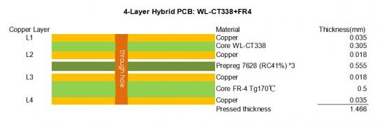
2. PCB Symmetrical Hybrid Stackup Structure
This hybrid 4-layer PCB stackup adopts symmetrical compression layout to eliminate warpage risk during high-temperature lamination and reflow soldering;WL-CT338 dielectric layers are arranged on outer signal layers for high-frequency trace routing, while FR4 cores form inner ground and power planes to balance cost and mechanical rigidity.
3. Key Differentiated Technical Advantages of WL-CT338 + FR4 Hybrid PCB
3.1 Balanced High-Frequency Electrical Performance & Cost Control
3.2 High Thermal Stability Matching for Lead-Free Solder Assembly
3.3 Immersion Gold (ENIG) Surface Finish Optimized for RF Applications
3.4 Zero Blind Via Design & Full Electrical Testing Guarantee
4. PCB Conclusion
This 4-layer WL-CT338 + TG170 FR4 hybrid ENIG PCB forms a cost-performance balanced mixed-signal circuit substrate solution that addresses the core pain point of traditional single-material PCBs: pure FR4 suffers excessive high-frequency signal loss while full high-frequency laminates bear high material costs. Through symmetrical hybrid stackup separation of RF and digital power layers, the product retains WL-CT338’s low-loss microwave transmission performance and leverages high-Tg FR4’s mature mechanical processing, thermal stability and cost advantages. Standardized through-via architecture, reliable immersion gold surface treatment and full electrical testing control guarantee consistent mass production quality, making it a universal high-performance substrate for satellite communication, airborne radar, phase array antenna and microwave power amplifier systems.
Supplementary Detailed CCL Knowledge: WL-CT338 Hydrocarbon Ceramic Copper Clad Laminate
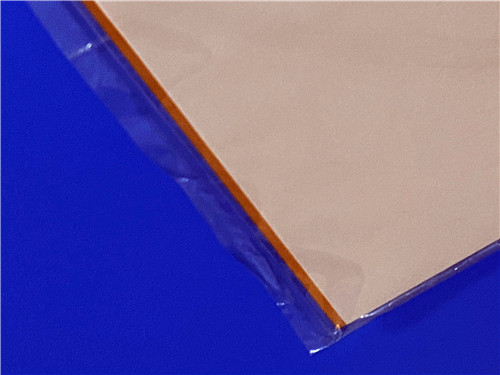
1.WL-CT338 Product Introduction
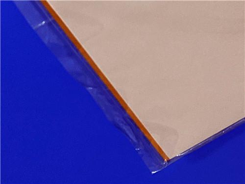
WL-CT338 is a high-performance organic polymer ceramic woven-glass fabric-reinforced copper-clad laminate developed by Taizhou Wangling Insulation Material Factory. This material belongs to the WL-CT series of hydrocarbon ceramic thermoset resin systems engineered to deliver exceptional low-loss dielectric properties while maintaining process compatibility with standard FR-4 manufacturing equipment. The composition features a hydrocarbon resin matrix reinforced with ceramic filler and woven glass fabric, creating a composite material that achieves an optimal balance of electrical performance, thermal stability, and mechanical strength.
The hydrocarbon ceramic resin system offers significant advantages over traditional PTFE-based high-frequency materials, including superior PCB processability, excellent dimensional stability, and consistent material performance across varying environmental conditions. The material's thermoset nature allows for multilayer lamination using conventional pressing cycles, eliminating the specialized handling requirements associated with thermoplastic fluoropolymer alternatives.
2.Key Advantages of WL-CT338
|
Test Item |
Test Condition |
Unit |
WL-CT338 Typical Value |
Test Standard Reference |
|
Typical Dielectric Constant (Dk) |
10GHz, Z-axis stripline method |
/ |
3.38 |
IPC-TM650 2.5.5.5, GB/T 12636-1990 |
|
Design Dielectric Constant (Dk) |
10GHz, 50Ω microstrip line |
/ |
3.55 |
IPC-TM650 2.5.5.5 |
|
Dk Tolerance |
Room temperature |
/ |
±0.05 |
Manufacturer internal standard |
|
Dissipation Factor (Df) |
2GHz |
/ |
0.0023 |
IPC-TM650 2.5.5.5 |
|
Dissipation Factor (Df) |
10GHz |
/ |
0.0029 |
IPC-TM650 2.5.5.5 |
|
Dissipation Factor (Df) |
20GHz |
/ |
0.0038 |
IPC-TM650 2.5.5.5 |
|
Dk Temperature Coefficient (TCDK) |
-55℃ ~ +150℃ |
PPM/℃ |
45 |
GB/T 4722-2017 |
|
Peel Strength (1oz ED Copper Foil) |
Room temperature |
N/mm |
1 |
IPC-TM650 2.4.8 |
|
Peel Strength (1oz RTF Copper Foil) |
Room temperature |
N/mm |
0.72 |
IPC-TM650 2.4.8 |
|
Volume Resistivity |
Ambient dry state |
MΩ·cm |
6×10⁹ |
IPC-TM650 2.3.1.1 |
|
Surface Resistivity |
Ambient dry state |
MΩ |
7×10⁸ |
IPC-TM650 2.3.1.1 |
|
Z-axis Electrical Strength |
5kV, 500V/s ramp |
KV/mm |
31 |
GB/T 4722-2017 |
|
XY Plane Breakdown Voltage |
5kV, 500V/s ramp |
KV |
30 |
GB/T 4722-2017 |
|
X/Y Axis CTE |
-55℃ ~ 288℃ |
ppm/℃ |
14, 16 |
IPC-TM650 2.4.41 |
|
Z Axis CTE |
-55℃ ~ 288℃ |
ppm/℃ |
50 |
IPC-TM650 2.4.41 |
|
Thermal Solder Float Resistance |
288℃, 10s, 3 cycles |
/ |
No delamination, no blister |
IPC-TM650 2.4.13 |
|
Water Absorption |
23.5±2℃, 24h immersion |
% |
0.04 |
IPC-TM650 2.6.2.1 |
|
Material Density |
Room temperature |
g/cm³ |
1.78 |
GB/T 1033.1 |
|
Continuous Operating Temperature |
Static thermal aging |
℃ |
-55 ~ +260 |
Manufacturer thermal cycle test |
|
Z-axis Thermal Conductivity |
Vertical direction |
W/(M·K) |
0.7 |
ASTM D5470 |
|
PIM Value (RTF Copper Match) |
Standard RF test fixture |
dBc |
≤-158 |
RF passive intermodulation industry standard |
|
Flammability Grade |
UL-94 vertical test |
Grade |
Non-flame retardant |
UL94 standard |
|
Glass Transition Temperature (Tg) |
DSC test |
℃ |
>280 |
IPC-TM650 2.4.25 |
|
Thermal Decomposition Temp (Td) |
TGA initial decomposition |
℃ |
421 |
IPC-TM650 2.4.24 |
|
Halogen Content |
XRF elemental test |
/ |
Halogen-free |
IPC-4101 halogen-free specification |
|
Core Dielectric Composition |
Material raw material analysis |
/ |
Hydrocarbon resin + ceramic filler + woven fiberglass cloth |
|
3.Full WL-CT338 Datasheet Technical Parameter Table
This complete datasheet table records all electrical, thermal, mechanical and environmental test indicators of WL-CT338, tested per IPC-TM-650 and GB/T standard methods for reference design simulation and PCB manufacturing verification.
|
Advantage Category |
Description |
Performance Benefit |
|
Low Dielectric Loss |
Df 0.0029 @10GHz |
Minimal signal attenuation for high-frequency designs |
|
Excellent Processability |
Thermoset resin system |
Compatible with standard FR-4 manufacturing processes |
|
Temperature Stability |
TCDK 45 ppm/℃ (-55℃ to +150℃) |
Consistent performance across wide operating range |
|
High Tg |
>280℃ |
Maintains dimensional stability under thermal stress |
|
Low CTE |
X/Y: 14-16 ppm/℃; Z: 50 ppm/℃ |
Excellent thermal-mechanical match with copper |
|
High Thermal Conductivity |
0.70 W/(m·K) |
Superior heat dissipation for power applications |
|
Low PIM |
≤-158 dBc (with RTF copper) |
Enables low passive intermodulation designs |
|
Radiation Resistance |
Irradiation-stable |
Suitable for aerospace and space applications |
|
Outgassing Performance |
Low volatile emissions |
Meets space vacuum outgassing requirements |
4.WL-CT338 Copper Foil & Dielectric Thickness Specification
4.1 WL-CT338 Dielectric Thickness with ED Copper
|
Thickness mm (mil) |
Tolerance mm (mil) |
|
0.102 mm (4 mil) |
±0.01 mm (0.4 mil) |
|
0.203 mm (8 mil) |
±0.025 mm (1.0 mil) |
|
0.305 mm (12 mil) |
±0.025 mm (1.0 mil) |
|
0.406 mm (16 mil) |
±0.038 mm (1.5 mil) |
|
0.508 mm (20 mil) |
±0.038 mm (1.5 mil) |
|
0.711 mm (28 mil) |
±0.05 mm (2.0 mil) |
|
0.813 mm (32 mil) |
±0.05 mm (2.0 mil) |
|
1.016 mm (40 mil) |
±0.076 mm (3.0 mil) |
|
1.524 mm (60 mil) |
±0.10 mm (4.0 mil) |
4.2 WL-CT338 Dielectric Thickness with RTF Copper
|
Thickness mm (mil) |
Tolerance mm (mil) |
Note |
|
0.221 mm (8.7 mil) |
±0.025 mm (1.0 mil) |
0.102mm + 0.018mm adhesive + 2×0.035mm copper |
|
0.526 mm (20.7 mil) |
±0.038 mm (1.5 mil) |
0.508mm + 0.018mm adhesive |
|
0.831 mm (32.7 mil) |
±0.051 mm (2.0 mil) |
0.813mm + 0.018mm adhesive |
|
1.034 mm (40.7 mil) |
±0.076 mm (3.0 mil) |
1.016mm + 0.018mm adhesive |
|
1.542 mm (60.7 mil) |
±0.10 mm (4.0 mil) |
1.524mm + 0.018mm adhesive |
|
2.05 mm (80.7 mil) |
±0.127 mm (5.0 mil) |
2.032mm + 0.018mm adhesive |
4.3 Available Panel Sizes
|
Dimension |
Available Options |
|
Standard Size |
460 × 610 mm (18 × 24 inches) |
|
Standard Size |
915 × 1220 mm (36 × 48 inches) |
5.WL-CT338 Typical Application Fields
6.WL-CT338 CCL Conclusion
WL-CT338 high-frequency copper clad laminate fills the market gap of cost-effective domesticlow-loss microwave substrates, breaking reliance on imported foreign high-frequency CCL materials. Its balanced advantages of ultra-low Dk/Df, ultra-high Tg, temperature-stable dielectric properties, FR4-compatible manufacturing flow and customizable copper foil options make it the optimal dielectric material for hybrid RF-digital PCB stackups like the4-layer WL-CT338 TG170 FR4hybrid PCB described above. With halogen-free formulation, radiation resistance and low vacuum outgassing characteristics, WL-CT338 satisfies strict reliability standards of aerospace and defense electronics, while standardized mass production capacity achieves better cost control compared with imported thermoplastic PTFE and hydrocarbon laminates, supporting large-scale commercialization of high-frequency communication and radar equipment.





Previous:
4-Layer F4BM265+S1000-2M Material Hyrbid PCB with Blind Via Impedance Control & ENIGNext:
6-Layer RO4003C + FR4 Mixed Dielectric PCB with Hard Gold Plating Blind ViaIf you have questions or suggestions,please leave us a message,we will reply you as soon as we can!
Categories
New Products

Wangling F4BTMS220 2-Layer DK2.2 PCB 10 mil Core with Immersion Gold

Wangling F4BTME350 10mil DK3.5 High Frequency Substrate PCB 2-Layer Immersion Gold

Wangling F4BTM300 Custom 2-layer PCB 20mil DK3.0 Substrate with Immersion Gold

Rogers 20mil RT/duroid 6202 2-layer ENIG High-Frequency Microwave PCB

Rogers 20mil AD250C PCB Pure Gold High-Frequency Antenna Circuit Board

8-Layer Hybrid RF PCB: RO4350B + TG170 FR-4 + RO4003C with RO4450F Bondply

4-Layer Rogers RO3010 Hybrid PCB Immersion Silver 2.8mm Finished Thickness

4-Layer 20mil Rogers RO3210 ISIG High-Frequency PCB with Controlled Depth Milling
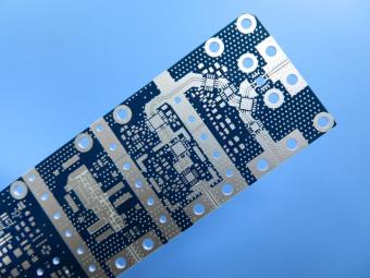
RO4003C exhibit a stable dielectric constant over a broad frequency range. This makes it an ideal substrate for broadband applications. And signal integrity performance improvement over the stack-ups with all FR4 board.
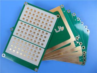
The hybrid PCB can be a mixture of FR-4 and high frequency material, and a mixture of high frequency material with different dielectric constant (DK)
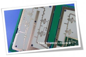
The 12mil core is on the top layer and it mainly plays the roles of signal layer. The core has fixed thickness which is very important to the electrical length of RF lines on the circuit board.
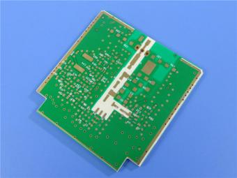
The hybrid PCB can be a mixture of FR-4 and high frequency material as abovementioned.
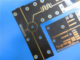
It contains 2 different boards in the panel. PCB boards are manufactured strictly as per required specifications with the standard IPC-Class-II.
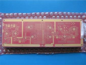
Hybrid PCB is also known as mixed material lamination, it’s normally combined by two different material like FR4 and PI(rigid flex PCB), FR4 and Ceramic, FR4 and Teflon, FR4 and Aluminum base etc.
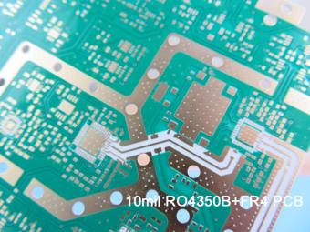
Hybrid constructions PCB typically involve a low loss material such as Nelco or Rogers combined with another core material like FR-4.
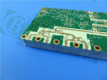
The Hybrid PCB on RO3003 and High Tg FR-4 is a state-of-the-art solution for high-frequency applications. With its exceptional stability, reliability, and manufacturability, it caters to the demands of industries such as automotive, telecommunications, and satellite communications.
 6-11C Shidai Jingyuan, Fuyong, Baoan, Shenzhen, Guangdong, China 518103


For inquiries about our products or pricelist, please leave to us and we will be in touch within 24 hours.
© Copyright: 2026 Shenzhen Bicheng Electronics Technology Co., Ltd.. All Rights Reserved.

IPv6 network supported


