

 Call Us Now !
Tel : +86 755 27374946
Call Us Now !
Tel : +86 755 27374946
 Order Online Now !
Email : info@bichengpcb.com
Order Online Now !
Email : info@bichengpcb.com
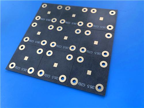
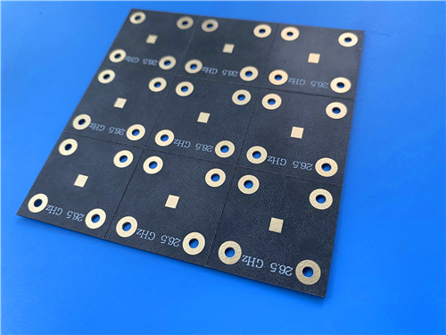
The 2-layer TLX-6 ENIG PCB with a 3.5 mil (0.089 mm) core represents a purpose-built, ultra-thin solution for high-frequency applications demanding low loss, stable Dk, and excellent PIM performance.
Item NO.:
BIC-617-v702Order(MOQ):
1-10Payment:
T/TProduct Origin:
ChinaShipping Port:
ShenzhenLead Time:
7-10 days
AGC Taconic TLX-6 PTFE Fiberglass Laminate PCB 2-layer 3.5mil ENIG Finish
This article provides a comprehensive technical description of a 2-layer rigid PCB fabricated on Taconic TLX-6, a PTFE fiberglass-reinforced high-frequency laminate with a 0.089 mm (3.5 mil) dielectric core and ENIG (Electroless Nickel Immersion Gold) surface finish.
The first part covers the PCB construction, layer stackup, design statistics, manufacturing quality, and target applications. The second part presents a detailed technical reference for theTLX-6 copper-clad laminate (CCL) material, including a complete data sheet, outgassing properties, available configurations, and material characteristics.
The 2-layer TLX-6 PCB is an ultra-thin, high-frequency rigid circuit board engineered for microwave and RF applications where low loss, phase stability, and passive intermodulation (PIM) performance are critical. Built on a 0.089 mm (3.5 mil) TLX-6 core — a polytetrafluoroethylene (PTFE) laminate reinforced with woven fiberglass cloth — this board delivers a dielectric constant (Dk) of 2.65 at 10 GHz with a tight tolerance of ±0.04, and a low dissipation factor (Df) of 0.0016 at 1.9 GHz and 0.0022 at 10 GHz. The finished board thickness is just 0.2 mm, with 1 oz (35 μm) copper on both outer layers and an ENIG surface finish for excellent solderability, flat coplanarity, and oxidation resistance.
The ultra-thin 3.5 mil core makes this board particularly suitable for coupler-type applications and compact microwave circuits where thin substrate profiles are required. Unlike conventional FR-4 boards, whose dielectric properties drift significantly at microwave frequencies and over temperature, the TLX-6 substrate maintains stable Dk with approximately ±2% variation from −55 °C to +125 °C. This stability, combined with the material's excellent PIM performance (measured below −160 dBc at 20 W per channel, 800 and 1800 MHz), makes the board well suited for antenna feed networks, power amplifiers, and high-power RF components where signal purity is essential.
· Dielectric constant (Dk): 2.65 ± 0.04 at 10 GHz, enabling consistent impedance control in 50 Ω transmission lines.
· Dissipation factor (Df): 0.0016 at 1.9 GHz and 0.0022 at 10 GHz — low loss for high-frequency signal transmission.
· Dk temperature stability: approximately ±2% variation from −55 °C to +125 °C.
· PIM performance: below −160 dBc (measured at 20 W per channel @ 800 and 1800 MHz).
· Ultra-thin core: 0.089 mm (3.5 mil) dielectric, ideal for coupler and compact microwave designs.
· Aerospace-grade outgassing: TML 0.09%, CVCM <0.01%, WVR 0.06% per ASTM E 595.
· UL 94 V-0 flammability rating; low moisture absorption for high-humidity environments.
The table below summarizes the physical dimensions, fabrication capabilities, surface finish, and quality-control specifications for this 2-layer Taconic TLX PCB, providing a complete snapshot of its construction parameters.
|
Parameter |
Specification |
|
Base Material |
TLX-6 (PTFE fiberglass laminate) |
|
Layer Count |
2 layers |
|
Board Dimensions |
105 mm × 98 mm (1 PCS), ±0.15 mm |
|
Minimum Trace / Space |
5 / 7 mils |
|
Minimum Hole Size |
0.3 mm |
|
Blind Vias |
None |
|
Finished Board Thickness |
0.2 mm |
|
Finished Copper Weight |
1 oz (1.4 mils / 35 μm), outer layers |
|
Via Plating Thickness |
20 μm |
|
Surface Finish |
ENIG (Immersion Gold) |
|
Top Silkscreen |
White |
|
Bottom Silkscreen |
None |
|
Top Solder Mask |
None |
|
Bottom Solder Mask |
None |
|
Electrical Test |
100% tested prior to shipment |
|
Artwork Format |
Gerber RS-274-X |
|
Quality Standard |
IPC-Class-2 |
|
Availability |
Worldwide |
The board employs a symmetric 2-layer rigid stackup with equal 1 oz copper cladding on both sides of a single TLX-6 dielectric core, as detailed in the table below.
|
Layer |
Material |
Thickness |
|
Layer 1 (Top) |
Copper |
35 μm (1 oz) |
|
Core |
TLX-6 (PTFE fiberglass) |
0.089 mm (3.5 mil) |
|
Layer 2 (Bottom) |
Copper |
35 μm (1 oz) |
The design statistics below reflect the board's component count, pad configuration, via density, and net structure, offering a quick quantitative snapshot of the circuit's complexity.
|
Metric |
Count |
|
Components |
102 |
|
Total Pads |
98 |
|
Through-Hole Pads |
61 |
|
Top SMT Pads |
37 |
|
Bottom SMT Pads |
0 |
|
Vias |
127 |
|
Nets |
2 |
The combination of ultra-low loss, stable Dk over temperature, excellent PIM performance, and aerospace-grade reliability makes thisTLX-6 PCB suitable for a broad range of high-frequency applications:
· Antenna systems and feed networks, including base station antennas and phased-array radar
· Couplers, splitters, combiners, and power dividers (especially thin-substrate coupler designs)
· Power amplifiers and low-noise amplifiers
· Microwave test equipment and transmission devices
· Mobile communications infrastructure
· Aerospace and avionics RF electronics (NASA-listed low outgassing material)
· Warship and naval antenna systems (extreme maritime environment resistance)
· Altimeter and flight instrument substrates (wide temperature range operation)
The 2-layer TLX-6 ENIG PCB with a 3.5 mil (0.089 mm) core represents a purpose-built, ultra-thin solution for high-frequency applications demanding low loss, stable Dk, and excellent PIM performance. Its PTFE-fiberglass substrate delivers a Dk of 2.65 with ±0.04 tolerance and a Df as low as 0.0016 at 1.9 GHz, while the symmetric 2-layer stackup with 1 oz copper and ENIG finish ensures reliable fabrication and assembly.
With IPC-Class-2 quality assurance, 100% electrical testing, and a material platform with aerospace-grade outgassing and UL 94 V-0 rating, this Taconic high frequencyboard is well positioned for antenna systems, couplers, power amplifiers, and microwave RF components where performance consistency across extreme environmental conditions is essential. The board's simple 2-layer architecture, combined with the exceptional high-frequency properties of TLX-6, offers a cost-effective yet high-performance platform for designers seeking FR-4 alternatives in the microwave frequency range.
Part II: TLX-6 Copper-Clad Laminate (CCL) — Technical Reference
The TLX series is a family of PTFE fiberglass-reinforced microwave substrates manufactured by AGC (formerly Taconic), designed for high-volume antenna and RF applications. The TLX series offers reliability across a wide range of RF applications, with dielectric constants ranging from 2.45 to 2.65 and a broad selection of available thicknesses and copper claddings. It is particularly suitable for low layer count microwave designs where mechanical reinforcement is required.
The woven fiberglass reinforcement in TLX laminates provides mechanical strength wherever a substrate experiences severe environments, including: resistance to creep for PWBs bolted to housings encountering high vibration during space launch; high temperature exposure in engine modules; radiation resistance in space (NASA-listed low outgassing material); resistance to extreme maritime environments for warship antennas; and resistance to wide temperature ranges for altimeter substrates during flight. TLX has a long space heritage and is used wherever a woven fiberglass reinforcement is required.
TLX-6, with a Dk of 2.65, is the highest-Dk member of the TLX family and is noteworthy for its availability as a very thin laminate (down to 0.089 mm / 3.5 mil), making it ideal for coupler-type applications. The surface of TLX has been optimized for copper adhesion, and the material can be combined with any of AGC's available copper claddings.
· Excellent PIM values in PCBs (measured below −160 dBc at 20 W per channel, 800 and 1800 MHz)
· Excellent mechanical and thermal properties with woven fiberglass reinforcement
· Low and stable Dk: 2.65 ± 0.04 at 10 GHz; ~±2% variation from −55 °C to +125 °C
· Low Df: 0.0016 at 1.9 GHz and 0.0022 at 10 GHz
· Dimensionally stable with low moisture absorption
· UL 94 V-0 flammability rating
· Aerospace-grade outgassing per ASTM E 595 (NASA-listed)
· Available in ultra-thin profiles down to 0.089 mm (3.5 mil) for coupler applications
· Suitable for low layer count microwave designs; wide range of thicknesses and copper claddings
The following table presents the complete electrical, thermal, and physical property data for the TLX-6 laminate. All values are typical measurements tested per IPC-TM-650 or ASTM standard methods, and are intended to assist customers in material selection.
|
Property |
Test Method |
Condition / Unit |
TLX-6 Typical Value |
|
Dk @ 10 GHz |
IPC-650 2.5.5.3 |
— |
2.65 |
|
Dk Tolerance |
— |
— |
±0.04 |
|
Df @ 1.9 GHz |
IPC-650 2.5.5.5.1 |
— |
0.0016 |
|
Df @ 10 GHz |
IPC-650 2.5.5.5.1 |
— |
0.0022 |
|
Dk Variation over Temp. |
— |
−55 °C to +125 °C |
~±2% |
|
Outgassing (% TML) |
ASTM E 595 |
24 h, 257 °F, ≤5×10⁻⁵ Torr |
0.09 |
|
Outgassing (% CVCM) |
ASTM E 595 |
24 h, 257 °F, ≤5×10⁻⁵ Torr |
<0.01 |
|
Outgassing (% WVR) |
ASTM E 595 |
24 h, 257 °F, ≤5×10⁻⁵ Torr |
0.06 |
|
Flammability |
UL 94 |
— |
V-0 |
|
PIM Performance |
PCB coupon test |
20 W/ch @ 800 & 1800 MHz |
<−160 dBc |
|
Dk Range (TLX family) |
— |
— |
2.45 – 2.65 |
|
Material Composition |
— |
— |
PTFE + woven fiberglass |
Notes: (1) Dk and Df values are measured per IPC-TM-650 test methods. (2) Outgassing data as reported by NASA (see http://outgassing.nasa.gov). (3) PIM measurement using manufactured PCB coupon with 20 watts per channel at 800 and 1800 MHz. (4) If more temperature stability is required, TSM-DS3 should be considered. (5) All data are typical measurements intended to assist material selection and do not constitute an express or implied warranty.
|
Designation |
Dk |
Dielectric Thickness (inches) |
Dielectric Thickness (mm) |
|
TLX-6 |
2.65 ± 0.04 |
0.0035 – 0.250 |
0.089 – 6.35 |
TLX can be combined with any of AGC's available copper claddings. The surface of TLX has been optimized for copper adhesion, ensuring reliable peel strength even under thermal cycling. Customers should consult AGC's Product Selector Guide for information on available copper cladding options, including standard electrodeposited (ED) foil and reverse-treated foil (RTF) for reduced conductor loss at microwave frequencies.
Standard panel sizes for TLX-6 laminate include the following; custom sizes may be available upon request.
|
Inches |
mm |
|
12 × 18 |
304 × 457 |
|
16 × 18 |
406 × 457 |
|
18 × 24 |
457 × 610 |
|
16 × 36 |
406 × 914 |
|
24 × 36 |
610 × 914 |
|
18 × 48 |
457 × 1220 |
|
36 × 48 |
914 × 1220 |
An example of the TLX-6 part number is: TLX-6-0310-CH/CH — 18" × 24" (457 mm × 610 mm), where the designation encodes the material type (TLX-6), dielectric thickness code (0310), and copper cladding configuration on both sides (CH/CH). This naming convention allows customers to specify exact material configurations for repeatable procurement.
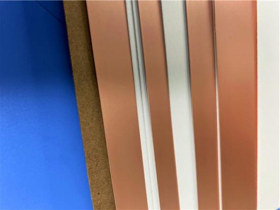
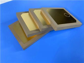
The image below shows the TLX-6 copper-clad laminate material, illustrating its physical appearance as a high-frequency PTFE-fiberglass composite substrate with copper foil cladding.
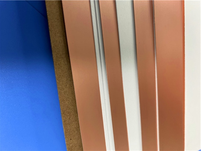
Figure 1: TLX-6 Copper-Clad Laminate
TLX-6 is a proven, high-volume PTFE fiberglass-reinforced microwave substrate that combines low and stable dielectric properties (Dk 2.65 ± 0.04, Df 0.0016–0.0022) with excellent mechanical robustness, aerospace-grade outgassing (TML 0.09%, CVCM <0.01%), and outstanding PIM performance below −160 dBc. Its availability in ultra-thin profiles down to 0.089 mm (3.5 mil), combined with a wide range of thickness options up to 6.35 mm and multiple copper cladding choices, makes it a versatile platform for couplers, antennas, power amplifiers, and other low-layer-count microwave designs.
With a long heritage in space, defense, and communications applications — including NASA-listed low outgassing certification and UL 94 V-0 flammability rating — TLX-6 remains a reliable workhorse substrate for engineers seeking consistent RF performance under extreme environmental conditions. The material's tightly controlled Dk (±0.04) and low loss characteristics ensure design repeatability across production volumes, making it well suited for both prototyping and high-volume manufacturing of RF and microwave components.





Previous:
Taconic TLX-8 PCB 50mil ENIG 2-Layer High-Frequency RF Circuit BoardNext:
AGC TLX-8 PCB 30mil Pure Gold 2-Layer Rigid Microwave Circuit BoardIf you have questions or suggestions,please leave us a message,we will reply you as soon as we can!
Categories
New Products
Wangling TP2200 PCB 0.8mm Substrate Immersion Gold 2-Layer High-Dk (Dk 22) RF Board
Rogers TMM10 PCB 5.08mm Core ENIG 2-Layer High-Dk Microwave Board
Taconic TLX-8 PCB 50mil ENIG 2-Layer High-Frequency RF Circuit Board
Wangling TF440 25mil DK4.4 Laminate Immersion Gold 2-Layer Copper-filling Vias PCB
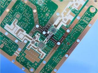
RO4360G2 Rogers 12mil ENEPIG 2-Layer DK6.15 High Frequency Custom PCB

Wangling F4BTMS220 2-Layer DK2.2 PCB 10 mil Core with Immersion Gold

Wangling F4BTME350 10mil DK3.5 High Frequency Substrate PCB 2-Layer Immersion Gold

Wangling F4BTM300 Custom 2-layer PCB 20mil DK3.0 Substrate with Immersion Gold
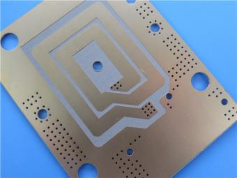
RF-35TC is a type of high frequency material from Taconic company. It offers a "best in class" low dissipation factor with high thermal conductivity.
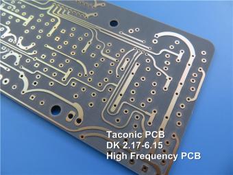
TLX offers reliability in a wide range of RF applications. This material is versatile due to its 2.45 - 2.65 DK range and available thicknesses and copper cladding. It is suitable for low layer count microwave designs.
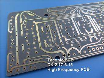
TLF-35A is another type of low cost RF material. It's the best choice for low cost, high volume commercial microwave and radio frequency applications.
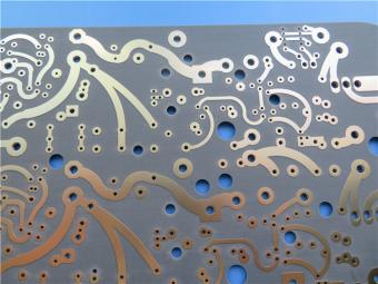
CER-10 is an organic-ceramic DK-10 laminate in the ORCER family of Taconic products. It is based on a woven glass reinforcement. CER-10 exhibits exceptional interlaminar bond strength and solder resistance.
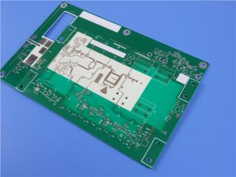
RO4360G2 laminates of Rogers Corporation are 6.15 Dk, low loss, glass-reinforced, hydrocarbon ceramic-filled thermoset materials that provide the ideal balance of performance and processing ease.
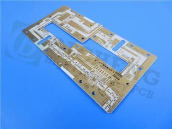
RF-60A is an organic-ceramic laminate in the ORganic CERamic(ORCER) family of Taconic products.
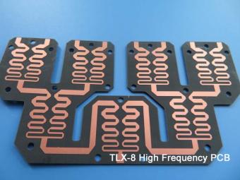
TLX is PTFE based fiberglass laminate, it is ideal for use in radar systems, mobile communications, microwave test equipment, microwave transmission devices and RF components.
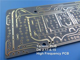
TLX offers reliability in a wide range of RF applications. This material is versatile due to its 2.45 - 2.65 DK range and available thicknesses and copper cladding. It is suitable for low layer count microwave designs
 6-11C Shidai Jingyuan, Fuyong, Baoan, Shenzhen, Guangdong, China 518103


For inquiries about our products or pricelist, please leave to us and we will be in touch within 24 hours.
© Copyright: 2026 Shenzhen Bicheng Electronics Technology Co., Ltd.. All Rights Reserved.

IPv6 network supported


