

 Call Us Now !
Tel : +86 755 27374946
Call Us Now !
Tel : +86 755 27374946
 Order Online Now !
Email : info@bichengpcb.com
Order Online Now !
Email : info@bichengpcb.com
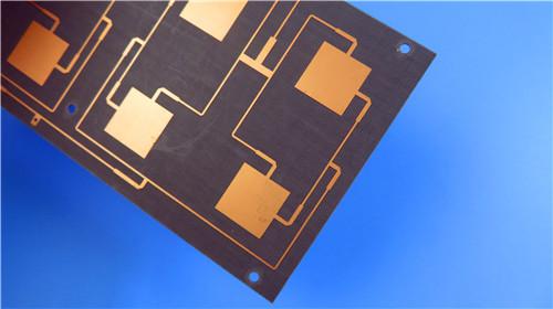
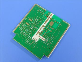
The 2-layer F4BME220 Immersion Gold PCB with a 0.1 mm core is a purpose-built solution for high-frequency applications demanding ultra-low Dk, minimal insertion loss, and compact form factor.
Item NO.:
BIC-612v697Order(MOQ):
1-10Payment:
T/TProduct Origin:
ChinaShipping Port:
ShenzhenLead Time:
7-10 days
Wangling 2-Layer F4BME220 PCB 3.9 mil DK 2.2 Laminate Immersion Gold Surface Finish
This article provides a comprehensive technical description of a 2-layer rigid PCB fabricated on Wangling F4BME220, a PTFE-glass-fiber high-frequency laminate with a 0.1 mm (3.9 mil) dielectric core and Immersion Gold surface finish. Part I covers the PCB construction, stackup, design statistics, manufacturing quality, and applications. Part II presents a detailed CCL technical reference including a complete data sheet, available configurations, and material characteristics.
The 2-layer F4BME220 PCB is an ultra-thin, high-frequency rigid circuit board for microwave and RF applications where low loss and compact form factor are critical. Built on a 0.1 mm (3.9 mil) F4BME220 core — a PTFE laminate reinforced with glass fiber cloth and clad with RTF copper — this board delivers Dk 2.2 at 10 GHz (±0.04) and Df 0.001 at 10 GHz (0.0014 at 20 GHz). Finished thickness is just 0.1 mm, with 1 oz (35 μm) copper on both layers and Immersion Gold finish.
Dk 2.2 places F4BME220 at the low end of PTFE laminates, ideal for wide-bandwidth, low-dispersion lines. Unlike FR-4, it maintains stable Dk and low loss at microwave frequencies. Its 0.1 mm thickness — among the thinnest rigid RF substrates — enables compact assemblies for phased-array antennas, satellite modules, and portable microwave equipment. RTF copper reduces conductor loss and delivers PIM ≤ −159 dBc, a key differentiator for high-linearity RF front-ends.
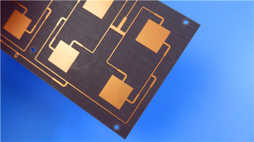
· Dk 2.2 ± 0.04 at 10 GHz — among the lowest in glass-fiber-reinforced PTFE laminates.
· Df 0.001 at 10 GHz, 0.0014 at 20 GHz — ultra-low insertion loss.
· PIM ≤ −159 dBc (RTF copper) — minimal intermodulation distortion.
· Ultra-thin 0.1 mm finished thickness (3.9 mil core).
· Operating range −55 °C to +260 °C; UL-94 V-0; moisture absorption ≤ 0.08 %.
· Immersion Gold finish — flat, coplanar, oxidation-resistant.
The table below summarizes the physical dimensions, fabrication parameters, and quality specifications.
|
Parameter |
Specification |
|
Board Dimensions |
79 mm × 65.3 mm (1 PCS), ±0.15 mm |
|
Minimum Trace / Space |
5 / 8 mils |
|
Minimum Hole Size |
0.25 mm |
|
Blind Vias |
None |
|
Finished Board Thickness |
0.1 mm (3.9 mil) |
|
Finished Copper Weight |
1 oz (1.4 mils / 35 μm), outer layers |
|
Via Plating Thickness |
20 μm |
|
Surface Finish |
Immersion Gold |
|
Top / Bottom Silkscreen |
White / None |
|
Top / Bottom Solder Mask |
Green / None |
|
Electrical Test |
100 % tested prior to shipment |
|
Artwork Format |
Gerber RS-274-X |
|
Quality Standard |
IPC-Class-2 |
|
Availability |
Worldwide |
The board uses a symmetric 2-layer stackup with equal 1 oz copper on both sides of the F4BME220 core.
|
Layer |
Material |
Thickness |
|
Layer 1 (Top) |
Copper (RTF) |
35 μm (1 oz) |
|
Core |
F4BME220 (PTFE + glass fiber) |
0.1 mm (3.9 mil) |
|
Layer 2 (Bottom) |
Copper (RTF) |
35 μm (1 oz) |
The design statistics below provide a quantitative snapshot of the circuit's complexity.
|
Metric |
Count |
|
Components |
23 |
|
Total Pads |
26 |
|
Through-Hole Pads |
14 |
|
Top SMT Pads |
12 |
|
Bottom SMT Pads |
0 |
|
Vias |
37 |
|
Nets |
2 |
This Wangling PCB uses established PTFE laminate processing. F4BME220's dimensional stability (CTE 25–34 ppm/°C X/Y) ensures registration accuracy, demonstrated by 5/8 mil trace/space and 0.25 mm minimum hole. The 0.1 mm core requires careful handling during lamination and drilling.
All boards are 100 % electrically tested and produced to IPC-Class-2 with Gerber RS-274-X artwork. Immersion Gold provides a flat, coplanar surface for fine-pitch SMT and RF connectors, with superior shelf life over HASL. The single-sided green solder mask and white top silkscreen leave the bottom bare to minimize dielectric discontinuities in RF-critical areas.
· Phased-array antenna elements and feed networks.
· Satellite communication payloads and ground terminals (Ku/Ka bands).
· Power dividers, couplers, and combiners.
· Phase shifters, passive components, and base station antennas.
· Portable and airborne microwave equipment.
The 2-layer F4BME220 Immersion Gold PCB with a 0.1 mm core is a purpose-built solution for high-frequency applications demanding ultra-low Dk, minimal insertion loss, and compact form factor. Its PTFE-glass-fiber substrate delivers Dk 2.2 ±0.04 and Df as low as 0.001 at 10 GHz, while RTF copper provides PIM ≤ −159 dBc. With IPC-Class-2 quality, 100 % electrical testing, and a −55 °C to +260 °C rating, this board is well positioned for phased-array antennas, satellite communications, and microwave RF systems where low Dk, low loss, and thin profile are essential.
Part II: F4BME220 Copper-Clad Laminate (CCL) — Technical Reference
F4BME series laminates are manufactured by pressing fiberglass cloth, PTFE resin, and PTFE film. Compared to the earlier F4B generation, F4BME offers a wider Dk range, lower loss, higher insulation resistance, and enhanced stability — a viable substitute for imported high-frequency laminates.
F4BM and F4BME share the same dielectric but differ in copper: F4BM uses ED copper for non-PIM applications, while F4BME uses RTF copper for PIM ≤ −159 dBc, precise line control, and lower conductor loss. Dk is tuned by the PTFE-to-glass ratio: higher Dk grades contain more glass for better stability at modestly higher loss. F4BME220 (Dk 2.2) is optimized for minimum loss and maximum bandwidth.
· Dk 2.17–3.0 across the series; customizable for specific applications.
· Ultra-low Df (0.001 at 10 GHz).
· RTF copper with PIM ≤ −159 dBc.
· Diversified panel sizes and thicknesses.
· Radiation resistance and low outgassing for aerospace.
· Minimum dielectric thickness 0.1 mm.
The table below presents complete electrical, mechanical, thermal, and physical property data for F4BME220. All values are typical measurements per IPC-TM-650 or GB/T 4722-2017.
|
Property |
Test Condition |
Unit |
F4BME220 |
|
Dk (Typical) |
10 GHz |
— |
2.2 |
|
Dk Tolerance |
— |
— |
±0.04 |
|
Df (Typical) |
10 GHz |
— |
0.001 |
|
Df (Typical) |
20 GHz |
— |
0.0014 |
|
Dk Temp. Coefficient |
−55 °C ~ 150 °C |
ppm/°C |
−142 |
|
Peel Strength (F4BM, 1 oz) |
ED Cu |
N/mm |
>1.8 |
|
Peel Strength (F4BME, 1 oz) |
RTF Cu |
N/mm |
>1.6 |
|
Volume Resistivity |
Normal |
MΩ·cm |
≥6×10⁶ |
|
Surface Resistance |
Normal |
MΩ |
≥1×10⁶ |
|
Electrical Strength (Z) |
5 kW, 500 V/s |
kV/mm |
>23 |
|
Breakdown Voltage (XY) |
5 kW, 500 V/s |
kV |
>30 |
|
CTE (X, Y) |
−55 °C ~ 288 °C |
ppm/°C |
25 ~ 34 |
|
CTE (Z) |
−55 °C ~ 288 °C |
ppm/°C |
240 |
|
Thermal Stress |
260 °C, 10 s, 3 cycles |
— |
No delamination |
|
Water Absorption |
20±2 °C, 24 h |
% |
≤0.08 |
|
Density |
Room temp. |
g/cm³ |
2.18 |
|
Long-Term Use Temp. |
High/low temp. chamber |
°C |
−55 ~ +260 |
|
Thermal Conductivity |
Z direction |
W/(m·K) |
0.24 |
|
PIM Value |
F4BME only |
dBc |
≤−159 |
|
Flammability |
— |
UL-94 |
V-0 |
|
Material Composition |
— |
— |
PTFE + glass fiber; RTF Cu (F4BME) |
Notes: (1) Dk measured in Z direction by stripline method per GB/T 12636-1990 or IPC-TM-650 2.5.5.5. (2) Other properties per IPC-TM-650 or GB/T 4722-2017. (3) All values are typical measurements for material selection and do not constitute a warranty; customers must verify suitability for each application.
· F4BME (RTF): 0.5 oz (0.018 mm), 1 oz (0.035 mm) — low conductor loss, excellent PIM.
· F4BM (ED): 0.5 oz, 1 oz, 1.5 oz (0.05 mm), 2 oz (0.07 mm) — for non-PIM applications.
· Aluminum base (F4BME220-AL): shielding and thermal dissipation.
· Copper base (F4BME220-CU): maximum thermal conductivity for high-power RF.
F4BME220 substrate minimum dielectric thickness is 0.1 mm. Standard thicknesses and tolerances are listed below. Customers should specify whether thickness includes copper (total) or dielectric only.
|
Thickness (mm) |
Tolerance (mm) |
Thickness (mm) |
Tolerance (mm) |
|
0.1 |
±0.01 |
1.5 |
±0.06 |
|
0.127 |
±0.01 |
1.524 |
±0.06 |
|
0.2 |
±0.02 |
1.575 |
±0.06 |
|
0.25 |
±0.02 |
2.0 |
±0.08 |
|
0.5 |
±0.04 |
2.5 |
±0.08 |
|
0.508 |
±0.04 |
3.0 |
±0.09 |
|
0.762 |
±0.05 |
4.0 |
±0.10 |
|
0.8 |
±0.05 |
5.0 |
±0.10 |
|
1.0 |
±0.05 |
6.0 |
±0.12 |
|
|
|
8.0 ~ 12.0 |
±0.15 ~ ±0.20 |
F4BME can be supplied with a metal base (aluminum or copper) on one side and copper foil on the other, providing electromagnetic shielding and enhanced thermal dissipation. Models: F4BME220-AL (aluminum base) and F4BME220-CU (copper base).
|
Model |
Metal Base |
Density (g/cm³) |
Thermal Cond. (W/m·K) |
Base Thickness (mm) |
|
F4BME220-CU |
Purple copper / brass |
8.9 |
380 |
0.48, 0.98, 1.48, 1.98, 2.98, 3.98 |
|
F4BME220-AL |
Aluminum |
2.7 |
180 |
Custom (contact factory) |
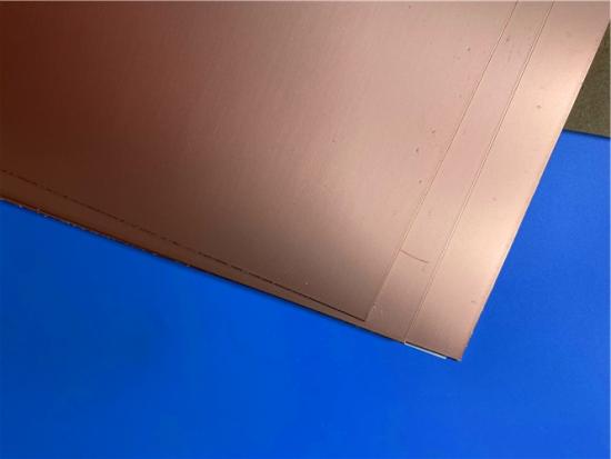
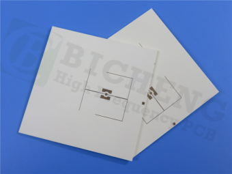
The image below shows the F4BME220 copper-clad laminate material.
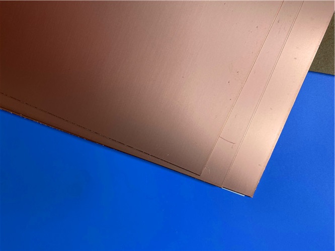
Figure 1: F4BME220 Copper-Clad Laminate
F4BME220 is a low-Dk (2.2), ultra-low-loss PTFE-glass-fiber laminate combining competitive electrical performance with practical manufacturability. Its Df of 0.001 at 10 GHz, PIM ≤ −159 dBc (RTF copper), and minimum dielectric thickness of 0.1 mm suit phased-array antennas, satellite communications, and wide-bandwidth microwave circuits. With thicknesses from 0.1 mm to 12 mm, multiple panel sizes, RTF/ED copper options, and aluminum/copper metal-backed variants, F4BME220 offers a flexible, cost-effective alternative to imported high-frequency laminates. Its UL-94 V-0 rating, −55 °C to +260 °C range, and low moisture absorption further support use in demanding industrial, aerospace, and telecommunications environments.





Previous:
Wangling 2-Layer F4BTMS300 PCB 0.127mm DK3.0 Laminate ENIG Surface FinishNext:
2-layer Isola I-Tera MT40 10mil Core PCB With Immersion SilverIf you have questions or suggestions,please leave us a message,we will reply you as soon as we can!
Categories
New Products

Wangling F4BTMS220 2-Layer DK2.2 PCB 10 mil Core with Immersion Gold

Wangling F4BTME350 10mil DK3.5 High Frequency Substrate PCB 2-Layer Immersion Gold

Wangling F4BTM300 Custom 2-layer PCB 20mil DK3.0 Substrate with Immersion Gold

Rogers 20mil RT/duroid 6202 2-layer ENIG High-Frequency Microwave PCB

Rogers 20mil AD250C PCB Pure Gold High-Frequency Antenna Circuit Board

8-Layer Hybrid RF PCB: RO4350B + TG170 FR-4 + RO4003C with RO4450F Bondply

4-Layer Rogers RO3010 Hybrid PCB Immersion Silver 2.8mm Finished Thickness

4-Layer 20mil Rogers RO3210 ISIG High-Frequency PCB with Controlled Depth Milling

RF-10 25mil Taconic PCB Materials stands out as a high-performance solution for RF applications. Its exceptional electrical properties, dimensional stability, thermal conductivity, and adhesion characteristics make it an ideal choice for demanding applications.
The PCB has a 4-layer hybrid stackup with a 0.5oz+plating ground layer, two 1oz ground layers, and a 0.5oz+plating signal layer.
The dimensions of the board are 55.00 x 26.00 mm, with a tolerance of +/- 0.15mm. The board has 16 components, 26 total pads, 9 through-hole pads, 10 top SMT pads, 7 bottom SMT pads, 77 vias, and 82 nets.
Rogers RO4003C PCB is an innovative and advanced circuit board that is made with high-quality materials.
The RO4350B PCB offers a range of benefits that make it an ideal choice for high-frequency applications. Its low dielectric loss and high thermal conductivity make it perfect for high-frequency applications such as RF and microwave circuits.
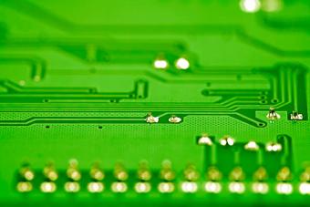
Bicheng PCB Ships High-Quality PCBs with Shengyi Tg150 ℃ S1000H Material and Advanced Stackup
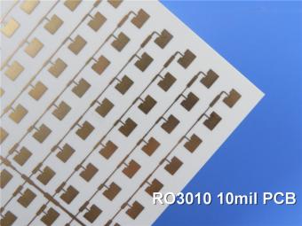
Rogers RO3010 PCB is ideal for a wide range of high-frequency applications, including power amplifiers, filters, couplers, and antennas.
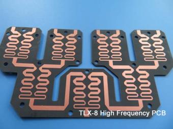
TLX-8 features low dielectric loss, low moisture absorption, and excellent thermal stability, making it ideal for high-frequency and high-speed applications. It has a low dissipation factor, which helps to minimize signal loss and distortion.
 6-11C Shidai Jingyuan, Fuyong, Baoan, Shenzhen, Guangdong, China 518103


For inquiries about our products or pricelist, please leave to us and we will be in touch within 24 hours.
© Copyright: 2026 Shenzhen Bicheng Electronics Technology Co., Ltd.. All Rights Reserved.

IPv6 network supported


