

 Call Us Now !
Tel : +86 755 27374946
Call Us Now !
Tel : +86 755 27374946
 Order Online Now !
Email : info@bichengpcb.com
Order Online Now !
Email : info@bichengpcb.com
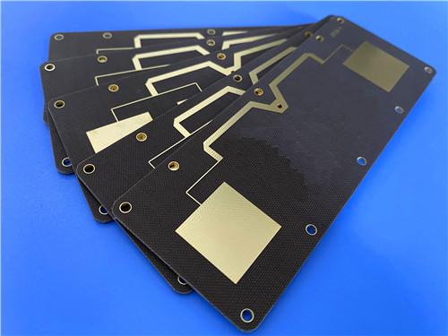

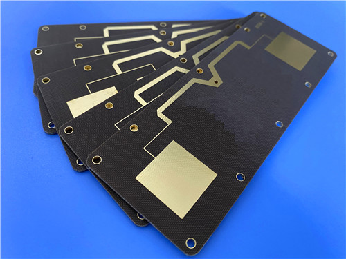
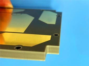
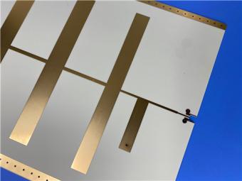
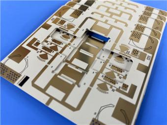
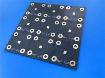
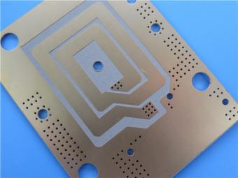
This 2-layer TLX-8 30mil PCB is a mature, standardized microwave circuit solution integrating AGC’s high-performance PTFE glass fiber substrate and high-reliability pure gold surface treatment.
Item NO.:
BIC-601-v686.0Order(MOQ):
1-10Payment:
T/TProduct Origin:
ChinaShipping Port:
ShenzhenLead Time:
7-10 days
AGC TLX-8 PCB 30mil Pure Gold2-Layer Rigid Microwave Circuit Board
Product Overview
Thiscontent delivers an in-depth, differentiated technical introduction to the 2-layer TLX-8 30mil pure gold PCB, splitting content into two independent core modules: finished PCB hardware introduction and dedicated TLX-8 copper-clad laminate (CCL) material analysis, with zero cross-repetition between sections.
The PCB segment systematically displays construction, stackup and circuit statistics via standardized concise tables, supplemented by manufacturing process logic, surface finish differentiation advantages, quality control standards and industry application scenarios.
The CCL chapter elaborates on AGC TLX-8 fiberglass-reinforced PTFE substrate raw material composition, full set of electrical, thermal, mechanical and environmental datasheet parameters via complete specification tables, structural design logic, extreme-environment performance advantages and material comparison differentiation. Each table is preceded by a concise summary sentence; standalone conclusion paragraphs are placed after the PCB section and CCL section respectively.
Part 1: Finished TLX-8 30mil Pure Gold PCB Complete Technical Introduction
1.1 PCB Core Construction Specification Table
This table centralizes all dimensional, manufacturing, surface treatment and testing hard specifications of the finished2-layer TLX-8 PCB, covering machining tolerance, line/hole process limits, copper thickness and post-production inspection rules.
|
Parameter |
Specification |
|
Board Dimensions |
76.4mm × 98.6mm per panel, ±0.15mm tolerance |
|
Minimum Trace/Space |
5/7 mils |
|
Minimum Hole Size |
0.3mm |
|
Blind Vias |
Not permitted |
|
Finished Board Thickness |
0.85mm |
|
Finished Copper Weight |
1 oz (1.4 mils) on outer layers |
|
Via Plating Thickness |
20 μm |
|
Surface Finish |
Pure Gold |
|
Top Silkscreen |
White |
|
Bottom Silkscreen |
No |
|
Top Solder Mask |
No |
|
Bottom Solder Mask |
No |
|
Electrical Testing |
100% prior to shipment |
|
Artwork Format |
Gerber RS-274-X |
1.2 PCB Internal Stackup Layer Structure Table
This table shows the symmetrical 2-layer rigid dielectric-copper stackup of the product, adopting single-core TLX-8 30mil substrate with identical 35μm copper cladding on both top and bottom sides.
|
Layer |
Material |
Thickness |
|
Copper Layer 1 |
Copper foil |
35 μm |
|
Dielectric Core |
Taconic TLX-8 PTFE Fiberglass |
0.762 mm (30 mils) |
|
Copper Layer 2 |
Copper foil |
35 μm |
1.3 PCB Circuit Layout Statistical Parameter Table
This table quantifies the complete circuit element distribution of the sample PCB, counting component mounting pads, through holes, vias and signal network quantity for assembly engineering reference.
|
Parameter |
Value |
|
Total Components |
30 |
|
Total Pads |
41 |
|
Through-Hole Pads |
25 |
|
Top SMT Pads |
16 |
|
Bottom SMT Pads |
0 |
|
Vias |
27 |
|
Nets |
2 |
1.4 Differentiated Product Core Advantages of This TLX-8 Pure Gold PCB
Unlike conventional FR-4 high-frequency boards and uncoated PTFE circuits, this finished PCB forms three exclusive competitive differentiators combining TLX-8 substrate and pure gold surface finish:
1) Ultra-low PIM RF performance foundation:
Supported byTLX-8 base material’s inherent PIM characteristic below -160 dBc, paired with pure gold surface finish to eliminate tin/copper oxidation interference that deteriorates passive intermodulation, suitable for high-power mobile communication passive components. Zero solder mask removes organic dielectric layer interference above radio frequency traces, reducing signal insertion loss under microwave frequency bands.
2) Extreme-environment mechanical stability:
The glass fiber reinforced TLX-8 core avoids creep deformation under long-term vibration load during aerospace launch; 20μm thick via plating and 1oz full copper outer layers maintain stable current transmission under high-temperature engine module operating conditions. Dimensional tolerance controlled at±0.15mm meets precision antenna assembly matching requirements.
3) Simplified assembly & wide compatibility:
Single-sided SMT layout with zero bottom pads reduces assembly fixture cost; white top silkscreen enables clear component marking without blocking gold contact surfaces; 100% electrical testing eliminates open/short circuit risks before global delivery, complying with IPC-Class-2 industrial reliability standards for radar, altimeter and shipborne antenna equipment.
1.5 Typical Target Application Scenarios for This PCB
The product is engineered for low-layer-count microwave hardware relying on stable high-frequency signal transmission, covering military, aerospace, industrial test and communication fields:
1.6 PCB Section Conclusion
This 2-layer TLX-8 30mil PCB is a mature, standardized microwave circuit solution integrating AGC’s high-performance PTFE glass fiber substrate and high-reliability pure gold surface treatment. All manufacturing dimensions, circuit layout and inspection standards are fully quantifiable with clear process boundaries, with differentiated design points including maskless bare gold circuit, single-sided SMT structure and anti-vibration reinforced substrate core. The product balances ultra-stable RF electrical performance and industrial mechanical durability, covering commercial to aerospace-grade medium-demanding microwave applications, and can support global mass customization based on the fixed 30mil dielectric thickness specification.
Part 2: In-Depth Analysis of AGC TLX-8 30mil PTFE Fiberglass CCL (Copper Clad Laminate)
2.1 TLX-8 CCL Material Basic Profile
TLX-8 is AGC’s mass-producible woven fiberglass reinforced PTFE copper-clad microwave substrate, positioned as a cost-effective universal RF base material for low-layer rigid PCB designs. The glass fiber woven fabric inside the composite solves the natural softness and poor dimensional stability of pure PTFE resin, delivering anti-creep, radiation-resistant and wide-temperature-range performance unavailable in ordinary epoxy substrates. Its dielectric constant is tightly controlled at 2.55±0.04 @10GHz with ultra-low dissipation factor, and material DK fluctuation only±2% from -55°C to 125°C, providing consistent signal performance across temperature cycling. It passes NASA low-outgassing testing, UL 94 V0 flame retardant certification, and is widely adopted for space, marine, automotive and radar RF hardware.
2.2 Complete TLX-8 CCL Datasheet Full Parameter Table
This table integrates electrical, dimensional stability, thermal, mechanical, chemical and flammability full performance indicators from officialAGC TLX-8 datasheets, with corresponding industry test standards for each metric to guarantee data authenticity.
|
Performance Category |
Test Property |
Test Condition |
Typical Value |
Unit |
Official Test Standard |
|
Electrical Core Properties |
Dielectric Constant (Dk) |
10 GHz, room temp |
2.55 ± 0.04 |
- |
IPC-650 2.5.5.3 |
|
Dissipation Factor (Df) |
10 GHz, room temp |
0.0018 |
- |
IPC-650 2.5.5.5.1 |
|
|
Surface Resistivity |
Elevated temperature aging |
6.605 × 10⁸ |
Mohm |
IPC-650 2.5.17.1 Sec.5.2.1 |
|
|
Surface Resistivity |
Humidity conditioning cycle |
3.550 × 10⁶ |
Mohm |
IPC-650 2.5.17.1 Sec.5.2.1 |
|
|
Volume Resistivity |
Elevated temperature aging |
1.110 × 10¹⁰ |
Mohm/cm |
IPC-650 2.5.17.1 Sec.5.2.1 |
|
|
Volume Resistivity |
Humidity conditioning cycle |
1.046 × 10¹⁰ |
Mohm/cm |
IPC-650 2.5.17.1 Sec.5.2.1 |
|
|
Dielectric Breakdown Voltage |
Standard specimen |
>45 |
kV |
IPC-650 2.5.6 |
|
|
Outgassing TML |
257°F, vacuum environment |
0.03 |
% |
ASTM E 595 (NASA space standard) |
|
|
Outgassing CVCM |
257°F, vacuum environment |
0 |
% |
ASTM E 595 |
|
|
Dimensional Stability |
MD Bake Dimensional Shift |
Post high-temperature baking |
0.06 |
mm/M |
IPC-650 2.4.39 Sec.5.4 |
|
CD Bake Dimensional Shift |
Post high-temperature baking |
0.08 |
mm/M |
IPC-650 2.4.39 Sec.5.4 |
|
|
MD Thermal Stress Shift |
Thermal cycling shock test |
0.09 |
mm/M |
IPC-650 2.4.39 Sec.5.5 |
|
|
CD Thermal Stress Shift |
Thermal cycling shock test |
0.1 |
mm/M |
IPC-650 2.4.39 Sec.5.5 |
|
|
Thermal Properties |
X-axis CTE (25–260°C) |
Linear thermal expansion |
21 |
ppm/°C |
IPC-650 2.4.41 / ASTM D 3386 |
|
Y-axis CTE (25–260°C) |
Linear thermal expansion |
23 |
ppm/°C |
IPC-650 2.4.41 / ASTM D 3386 |
|
|
Z-axis CTE (25–260°C) |
Thickness direction expansion |
215 |
ppm/°C |
IPC-650 2.4.41 / ASTM D 3386 |
|
|
2% Weight Loss Td |
TGA thermal decomposition |
535 |
°C |
IPC-650 2.4.24.6 |
|
|
5% Weight Loss Td |
TGA thermal decomposition |
553 |
°C |
IPC-650 2.4.24.6 |
|
|
Thermal Conductivity |
Standard substrate panel |
0.19 |
W/m·K |
ASTM F433 / ASTM 1530-06 |
|
|
Mechanical Properties |
1oz ED Copper Peel Strength |
Post thermal stress aging |
2.63 |
N/mm |
IPC-650 2.4.8 Sec.5.2.2 |
|
MD Young’s Modulus |
Room temperature tensile test |
6757 |
N/mm² |
ASTM D 902 |
|
|
CD Young’s Modulus |
Room temperature tensile test |
8274 |
N/mm² |
ASTM D 902 |
|
|
Chemical & Safety Properties |
Moisture Absorption |
Water immersion conditioning |
0.02 |
% |
IPC-650 2.6.2.1 |
|
Flammability Rating |
Vertical burn test |
V-0 |
Grade |
UL 94 |
2.3 TLX-8 CCL Exclusive Differentiated Material Advantages
Compared with ordinary unreinforced PTFE substrates and high-cost modified hydrocarbon laminates, TLX-8’s core material differentiation lies in balanced multi-performance tradeoffs without over-design:
1) Stable ultra-low-loss electrical characteristics:
Fixed Dk=2.55±0.04 and Df=0.0018@10GHz eliminate frequency drift of antenna gain; measured PIM value lower than -160 dBc under 20W per channel power at 800/1800MHz, meeting high-power communication passive component requirements.
2) Reinforced mechanical anti-deformation capability:
Woven glass fiber mesh restricts X/Y axis thermal expansion (21–23ppm/°C), resisting creep deformation under sustained bolted vibration loads for aerospace launch equipment; excellent peel strength avoids copper foil delamination during multi-cycle thermal shock.
3) Ultra-low environmental interference:
Only 0.02% moisture absorption rate prevents Dk shift caused by humidity changes; NASA-qualified low outgassing performance avoids contamination of precision space electronic components; 535°C initial thermal decomposition temperature adapts long-term high-temperature engine module working environments.
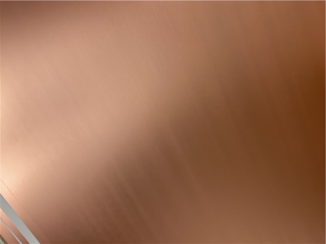
2.4 Wide Thickness & Panel Size Customization for Mass Production
2.5 CCL Application Matching Logic
TLX-8 is exclusively positioned for low-layer-count microwave PCB designs (2–4 layers recommended), not suitable for high-layer multi-stack complex boards due to Z-axis high CTE (215ppm/°C). The 30mil (0.762mm) core thickness selected for this PCB balances circuit impedance control and board rigidity, ideal for microstrip line antennas, directional couplers and power splitters requiring medium dielectric thickness. Material operating temperature window covers -55°C to 125°C with minor Dk variation, covering land, sea, air and space multi-scenario extreme temperature environments.
2.6 CCL Section Conclusion
AGC TLX-8 fiberglass-reinforced PTFE copper-clad laminate is a mature, versatile microwave base material with complete standardized datasheet performance verification. Its core competitiveness is the integration of ultra-stable high-frequency electrical parameters and glass fiber reinforced mechanical robustness, solving the fatal drawbacks of pure PTFE substrate’s poor rigidity and ordinary epoxy’s high dielectric loss at microwave bands. The 30mil thickness specification matched in this TLX-8 high frequency PCB is a mainstream universal thickness for low-layer RF circuits, with balanced cost, processability and environmental tolerance. As the foundational core of the finished pure gold PCB, TLX-8 determines the product’s inherent anti-vibration, low-loss and radiation-resistant performance, becoming the core differentiation point distinguishing this circuit board from conventional FR-4 and entry-level PTFE microwave PCBs.





Previous:
AGC Taconic TLX-6 PTFE Fiberglass Laminate PCB 2-layer 3.5mil ENIG FinishNext:
7.5mil AGC Taconic TLY-5 Substrate Custom PCB EPIG Finish Bare CopperIf you have questions or suggestions,please leave us a message,we will reply you as soon as we can!
Categories
New Products

8-Layer Hybrid RF PCB: RO4350B + TG170 FR-4 + RO4003C with RO4450F Bondply

4-Layer Rogers RO3010 Hybrid PCB Immersion Silver 2.8mm Finished Thickness

4-Layer 20mil Rogers RO3210 ISIG High-Frequency PCB with Controlled Depth Milling
4-Layer 10mil RO3003 + Tg170 FR-4 Hybrid PCB with ENIG and Controlled Depth Milling
2-Layer F4BM233 4.0mm Wangling Substrate High-Frequency Custom PCB with ENIG Finish
Wangling WL-CT615 8mil Ultra-Thin High-Frequency 2-Layer PCB ENEPIG Finish
High-Frequency 2-Layer PCB on 59mil Wangling TP440 Thermoplastic Dielectric Immersion Gold
AGC Taconic TLX-6 PTFE Fiberglass Laminate PCB 2-layer 3.5mil ENIG Finish
RF-35TC is a type of high frequency material from Taconic company. It offers a "best in class" low dissipation factor with high thermal conductivity.
TLX offers reliability in a wide range of RF applications. This material is versatile due to its 2.45 - 2.65 DK range and available thicknesses and copper cladding. It is suitable for low layer count microwave designs.
TLF-35A is another type of low cost RF material. It's the best choice for low cost, high volume commercial microwave and radio frequency applications.
CER-10 is an organic-ceramic DK-10 laminate in the ORCER family of Taconic products. It is based on a woven glass reinforcement. CER-10 exhibits exceptional interlaminar bond strength and solder resistance.
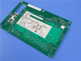
RO4360G2 laminates of Rogers Corporation are 6.15 Dk, low loss, glass-reinforced, hydrocarbon ceramic-filled thermoset materials that provide the ideal balance of performance and processing ease.
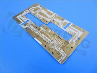
RF-60A is an organic-ceramic laminate in the ORganic CERamic(ORCER) family of Taconic products.
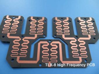
TLX is PTFE based fiberglass laminate, it is ideal for use in radar systems, mobile communications, microwave test equipment, microwave transmission devices and RF components.
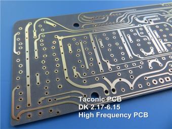
TLX offers reliability in a wide range of RF applications. This material is versatile due to its 2.45 - 2.65 DK range and available thicknesses and copper cladding. It is suitable for low layer count microwave designs
 6-11C Shidai Jingyuan, Fuyong, Baoan, Shenzhen, Guangdong, China 518103


For inquiries about our products or pricelist, please leave to us and we will be in touch within 24 hours.
© Copyright: 2026 Shenzhen Bicheng Electronics Technology Co., Ltd.. All Rights Reserved.

IPv6 network supported


