

 Call Us Now !
Tel : +86 755 27374946
Call Us Now !
Tel : +86 755 27374946
 Order Online Now !
Email : info@bichengpcb.com
Order Online Now !
Email : info@bichengpcb.com
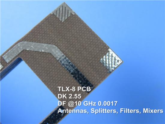
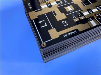
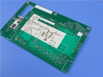
TLX is PTFE based fiberglass laminate, it is ideal for use in radar systems, mobile communications, microwave test equipment, microwave transmission devices and RF components.
Item NO.:
BIC-030-v56.0Order(MOQ):
1-10Payment:
T/TProduct Origin:
ChinaColor:
GreenShipping Port:
ShenzhenLead Time:
7-10 days
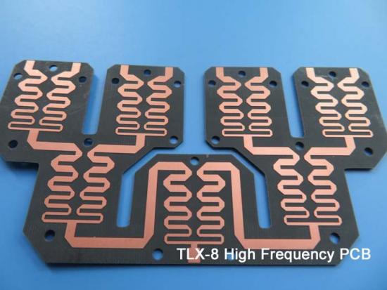
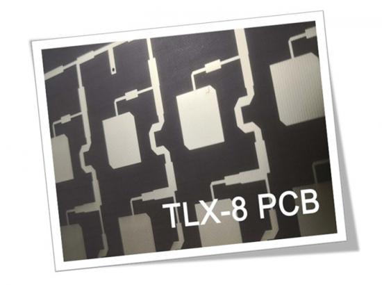
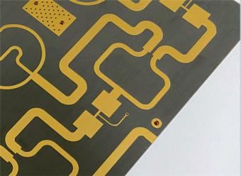
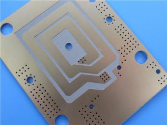
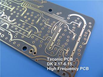
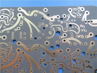
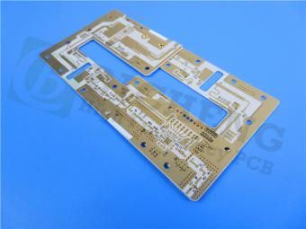
Taconic High Frequency PCB Buitl on TLX-8 62mil 1.575mm with OSP for Directional Couplers
(Printed Circuit Boards are custom-made products, the picture and parameters shown are just for reference)
TLX offers reliability in a wide range of RF applications. This material is versatile due to its 2.45 - 2.65 DK range and available thicknesses and copper cladding. It is suitable for low layer count microwave designs.
TLX is a workhorse in the RF microwave substrate world where the fiberglass offers mechanical reinforcement wherever a substrate experiences severe environments such as: resistance to creep for PCBs bolted to a housing that encounter high levels of vibration during space launch, high temperature exposure in engine modules, radiation resistance in space, antenna for warships that undergo extreme environments at sea and a substrate for altimeters that see a wide range of temperatures during flight.

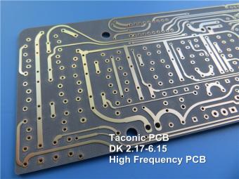
There're TLX-0 (dk2.45), TLX-9 (dk2.50), TLX-8 (dk2.55), TLX-7 (dk2.60) and TLX-6 (dk2.65) in the TLX family. Dielectric thickness of TLX-0 ranges from 0.127mm to 6.35mm (5mil-250mil), TLX-9 ranges from 0.05mm to 6.35mm (2mil - 250mil), TLX-8 ranges from 0.064mm to 6.35mm (2.5mil to 250mil), TLX-7 ranges from 0.089mm to 6.35mm (3.5mil - 250mil), TLX-6 ranges from 0.089mm to 6.35mm (3.5mil to 250mil).

Benefits:
Excellent mechanical & thermal properties
Low & stable DK
Dimensionally stable
Low moisture absorption
UL 94 V-O rating
Tightly controlled DK
Low DF
For low layer count microwave designs
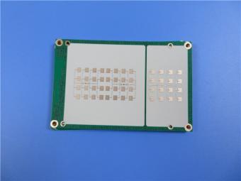
Applications:
Antennas
Couplers, Splitters, Combiners,
Amplifiers, Mixers, Filters
Passive components
PCB Specifications:
| PCB SIZE | 99 x 88mm=1PCS |
| BOARD TYPE | Double sided PCB |
| Number of Layers | 2 layers |
| Surface Mount Components | YES |
| Through Hole Components | NO |
| LAYER STACKUP | copper ------- 35um(1 oz)+plate TOP layer |
| TLX-8 1.575mm | |
| copper ------- 35um(1oz) + plate BOT Layer | |
| TECHNOLOGY | |
| Minimum Trace and Space: | 15 mil / 10 mil |
| Minimum / Maximum Holes: | 0.5mm/2.0mm |
| Number of Different Holes: | N/A |
| Number of Drill Holes: | N/A |
| Number of Milled Slots: | 0 |
| Number of Internal Cutouts: | 0 |
| Impedance Control: | no |
| Number of Gold finger: | 0 |
| BOARD MATERIAL | |
| Glass Epoxy: | TLX-8 1.575mm |
| Final foil external: | 1 oz |
| Final foil internal: | N/A |
| Final height of PCB: | 1.6 mm ±10% |
| PLATING AND COATING | |
| Surface Finish | OSP |
| Solder Mask Apply To: | N/A |
| Solder Mask Color: | N/A |
| Solder Mask Type: | N/A |
| CONTOUR/CUTTING | Routing |
| MARKING | |
| Side of Component Legend | N/A |
| Colour of Component Legend | N/A |
| Manufacturer Name or Logo: | N/A |
| VIA | N/A |
| FLAMIBILITY RATING | UL 94-V0 Approval MIN. |
| DIMENSION TOLERANCE | |
| Outline dimension: | 0.0059" |
| Board plating: | 0.0029" |
| Drill tolerance: | 0.002" |
| TEST | 100% Electrical Test prior shipment |
| TYPE OF ARTWORK TO BE SUPPLIED | email file, Gerber RS-274-X, PCBDOC etc |
| SERVICE AREA | Worldwide, Globally. |
Data Sheet of TLX-8:
| TLX-8 TYPICAL VALUES | |||||
| Property | Test Method | Unit | Value | Unit | Value |
| DK @10 GHz | IPC-650 2.5.5.3 | 2.55 | 2.55 | ||
| Df @1.9 GHz | IPC-650 2.5.5.5.1 | 0.0012 | 0.0012 | ||
| Df @10 GHz | IPC-650 2.5.5.5.1 | 0.0017 | 0.0017 | ||
| Dielectric Breakdown | IPC-650 2.5.6 | kV | >45 | kV | >45 |
| Moisture Absorption | IPC-650 2.6.2.1 | % | 0.02 | % | 0.02 |
| Flexural Strength(MD) | ASTM D 709 | psi | 28,900 | N/mm2 | |
| Flexural Strength(CD) | ASTM D 709 | psi | 20,600 | N/mm2 | |
| Tensile Strength(MD) | ASTM D 902 | psi | 35,600 | N/mm2 | |
| Tensile Strength(CD) | ASTM D 902 | psi | 27,500 | N/mm2 | |
| Elongation at Break(MD) | ASTM D 902 | % | 3.94 | % | 3.94 |
| Elongation at Break(CD) | ASTM D 902 | % | 3.92 | % | 3.92 |
| Young's Modulus(MD) | ASTM D 902 | kpsi | 980 | N/mm2 | |
| Young's Modulus(CD) | ASTM D 902 | kpsi | 1,200 | N/mm2 | |
| Young's Modulus(MD) | ASTM D 3039 | kpsi | 1,630 | N/mm2 | |
| Poisson's Ratio | ASTM D 3039 | 0.135 | N/mm | ||
| Peel Stength(1 oz.ed) | IPC-650 2.4.8 Sec.5.2.2(Thermal Stress.) | Ibs./linear inch | 15 | N/mm | |
| Peel Stength(1 oz.RTF) | IPC-650 2.4.8 Sec.5.2.2(Thermal Stress.) | Ibs./linear inch | 17 | N/mm | |
| Peel Stength(½ oz.ed) | IPC-650 2.4.8.3(Elevated Temp.) | Ibs./linear inch | 14 | N/mm | |
| Peel Stength(½ oz.ed) | IPC-650 2.4.8 Sec.5.2.2(Thermal Stress.) | Ibs./linear inch | 11 | N/mm | |
| Peel Stength(1 oz.rolled) | IPC-650 2.4.8 Sec.5.2.2(Thermal Stress.) | Ibs./linear inch | 13 | N/mm | 2.1 |
| Thermal Conductivity | ASTM F433/ASTM 1530-06 | W/M*K | 0.19 | W/M*K | 0.19 |
| Dimensional Stability(MD) | IPC-650 2.4.39 Sec.5.5(After Bake.) | mils/in. | 0.06 | mm/M | |
| Dimensional Stability(CD) | IPC-650 2.4.39 Sec.5.4(After Bake.) | mils/in. | 0.08 | mm/M | |
| Dimensional Stability(MD) | IPC-650 2.4.39 Sec.5.5(Thermal Stress.) | mils/in. | 0.09 | mm/M | |
| Dimensional Stability(CD) | IPC-650 2.4.39 Sec.5.5(Thermal Stress.) | mils/in. | 0.1 | mm/M | |
| Surface Resistivity | IPC-650 2.5.17.1 Sec.5.2.1(Elevated Temp.) | Mohm | 6.605 x 10⁸ | Mohm | 6.605 x 10⁸ |
| Surface Resistivity | IPC-650 2.5.17.1 Sec.5.2.1(Humidity Cond.) | Mohm | 3.550 x 10⁶ | Mohm | 3.550 x 10⁶ |
| Volume Resistivity | IPC-650 2.5.17.1 Sec.5.2.1(Elevated Temp.) | Mohm/cm | 1.110 x 10¹⁰ | Mohm/cm | 1.110 x 10¹⁰ |
| Volume Resistivity | IPC-650 2.5.17.1 Sec.5.2.1(Humidity Cond.) | Mohm/cm | 1.046 x 10¹⁰ | Mohm/cm | 1.046 x 10¹⁰ |
| CTE(X axis)(25-260℃) | IPC-650 2.4.41/ASTM D 3386 | ppm/℃ | 21 | ppm/℃ | 21 |
| CTE(Y axis)(25-260℃) | IPC-650 2.4.41/ASTM D 3386 | ppm/℃ | 23 | ppm/℃ | 23 |
| CTE(Z axis)(25-260℃) | IPC-650 2.4.41/ASTM D 3386 | ppm/℃ | 215 | ppm/℃ | 215 |
| Density(Specific Gravity) | ASTM D 792 | g/cm3 | 2.25 | g/cm3 | 2.25 |
| Td(2% Weight Loss) | IPC-650 2.4.24.6(TGA) | ℃ | 535 | ℃ | |
| Td(5% Weight Loss) | IPC-650 2.4.24.6(TGA) | ℃ | 553 | ℃ | |
| Flammability Rating | UL-94 | V-0 | V-0 | ||
MANUFACTURING PROCESS:

BICHENG PCB EQUIPMENT:

BICHENG PCB CERTIFICATION:

Previous:
Taconic High Frequency PCB Built on TLX-9 62mil 1.575mm With Immersion SilverNext:
RF-60A 25mil (0.635mm) Taconic High Frequency PCB With Immersion Ni/AuIf you have questions or suggestions,please leave us a message,we will reply you as soon as we can!
Categories
New Products
Wangling 5mil 0.127mm TFA300 Core 2-layer Immersion Gold Green Solder Mask PCB
7.5mil AGC Taconic TLY-5 Substrate Custom PCB EPIG Finish Bare Copper
10mil Rogers CuClad 250 Immersion Gold 2-Layer Rigid Microwave PCB
20mil F4BTMS450 Wangling DK4.5 Laminate Custom PCB HASL LF Finsh
F4BME275 Wangling DK2.75 Laminate 2-Layer 1.6mm Pure Gold RF Custom PCB
Wangling F4BTD350S High Frequency PCB 2-layer 20mil Thick ENIG DK3.5 Substrate

12-layer TG200 TU-872 SLK High-Speed FR4 1.68mm PCB with ENIG Impedance Control

12-Layer RO4350B + RO3010 3.14mm Hybrid PCB Nickel-Free EPIG Surface Finish Blind Via
RF-35TC is a type of high frequency material from Taconic company. It offers a "best in class" low dissipation factor with high thermal conductivity.
TLX offers reliability in a wide range of RF applications. This material is versatile due to its 2.45 - 2.65 DK range and available thicknesses and copper cladding. It is suitable for low layer count microwave designs.

TLF-35A is another type of low cost RF material. It's the best choice for low cost, high volume commercial microwave and radio frequency applications.
CER-10 is an organic-ceramic DK-10 laminate in the ORCER family of Taconic products. It is based on a woven glass reinforcement. CER-10 exhibits exceptional interlaminar bond strength and solder resistance.
RO4360G2 laminates of Rogers Corporation are 6.15 Dk, low loss, glass-reinforced, hydrocarbon ceramic-filled thermoset materials that provide the ideal balance of performance and processing ease.
RF-60A is an organic-ceramic laminate in the ORganic CERamic(ORCER) family of Taconic products.
TLX offers reliability in a wide range of RF applications. This material is versatile due to its 2.45 - 2.65 DK range and available thicknesses and copper cladding. It is suitable for low layer count microwave designs
RF-10 high frequency materials are engineered to provide a cost effective substrates, responding to a need in RF applications for size reduction.
 6-11C Shidai Jingyuan, Fuyong, Baoan, Shenzhen, Guangdong, China 518103


For inquiries about our products or pricelist, please leave to us and we will be in touch within 24 hours.
© Copyright: 2026 Shenzhen Bicheng Electronics Technology Co., Ltd.. All Rights Reserved.

IPv6 network supported


