

 Call Us Now !
Tel : +86 755 27374946
Call Us Now !
Tel : +86 755 27374946
 Order Online Now !
Email : info@bichengpcb.com
Order Online Now !
Email : info@bichengpcb.com
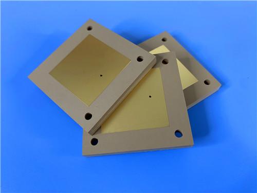
The 2-layer 100mil Rogers TMM3 PCB with EPIG surface finish represents a purpose-built solution for high-frequency applications demanding dielectric stability, thermal reliability, and signal integrity.
Item NO.:
BIC-611v696Order(MOQ):
1-10Payment:
T/TProduct Origin:
ChinaShipping Port:
ShenzhenLead Time:
7-10 days
2-Layer 100mil Rogers TMM3 Custom High FrequencyPCB with EPIG Surface Finish
This article presents a high-frequency 2-layer rigid PCB built on Rogers TMM3 thermoset microwave laminate at 100mil (2.54mm) thickness, finished with Electroless Palladium Immersion Gold (EPIG). Designed for RF and microwave applications requiring stable dielectric performance and high plated-through-hole (PTH) reliability, the board combines a ceramic-filled thermoset composite substrate with a nickel-free surface finish to deliver consistent electrical behavior across wide temperature ranges. With no solder mask and no silkscreen, the bare-board configuration minimizes dielectric interference at RF frequencies. Manufactured to IPC-Class-2 standards and subjected to 100% electrical testing prior to shipment, this PCB is available for worldwide deployment. The following sections detail the TMM3 100mil PCB construction, stackup, statistics, key features, and applications, followed by an in-depth technical reference on the TMM3 copper-clad laminate (CCL) material.
The 2-layer 100mil TMM3 PCB is a high-frequency rigid circuit board engineered for stripline and microstrip applications where dielectric stability and PTH reliability are critical. Built on Rogers TMM3 ceramic thermoset polymer composite, this board features a finished thickness of 2.54mm (100mil) with 1 oz (35um) copper on both outer layers. The EPIG surface finish — notably nickel-free — provides a flat, solderable, and wire-bondable surface ideal for high-frequency signal integrity. The board dimensions are 48.6mm x 50.04mm per piece, with a minimum hole size of 2.5mm and no blind vias. With no solder mask and no silkscreen on either side, the board presents bare copper and gold surfaces optimized for RF performance and minimal signal loss. The artwork is supplied in Gerber RS-274-X format, and every board undergoes 100% electrical testing before shipment to verify continuity and insulation integrity.
The table below summarizes the core physical and manufacturing specifications of this 2-layer TMM3 PCB, covering board dimensions, hole geometry, copper weight, surface finish, and quality control measures.
|
Parameter |
Specification |
|
Board Dimensions |
48.6 mm x 50.04 mm (1 PCS) |
|
Minimum Hole Size |
2.5 mm |
|
Blind Vias |
None |
|
Finished Board Thickness |
2.54 mm (100 mil) |
|
Finished Cu Weight (Outer) |
1 oz (1.4 mils / 35 um) |
|
Via Plating Thickness |
20 um |
|
Surface Finish |
EPIG (Electroless Palladium Immersion Gold, Ni-free) |
|
Top Silkscreen |
No |
|
Bottom Silkscreen |
No |
|
Top Solder Mask |
No |
|
Bottom Solder Mask |
No |
|
Electrical Test |
100% tested prior to shipment |
|
Artwork Format |
Gerber RS-274-X |
|
Accepted Standard |
IPC-Class-2 |
|
Availability |
Worldwide |
The stackup consists of a symmetrical two-layer rigid configuration with 35um copper cladding on both sides of a 100mil (2.54mm) Rogers TMM3 core, providing a balanced structure for high-frequency signal propagation and mechanical stability.
|
Layer |
Material |
Thickness |
|
Copper Layer 1 (Top) |
Electrodeposited Copper |
35 um (1 oz) |
|
Core Substrate |
Rogers TMM3 (Ceramic Thermoset Polymer) |
100 mil (2.54 mm) |
|
Copper Layer 2 (Bottom) |
Electrodeposited Copper |
35 um (1 oz) |
The design statistics reflect a compact, single-component board with minimal interconnect complexity, featuring one through-hole pad, one top-side SMT pad, one via, and two nets.
|
Metric |
Count |
|
Components |
1 |
|
Total Pads |
1 |
|
Through-Hole Pads |
1 |
|
Top SMT Pads |
1 |
|
Bottom SMT Pads |
0 |
|
Vias |
1 |
|
Nets |
2 |
Rogers TMM3 offers a process dielectric constant (Dk) of 3.27 +/- 0.032 at 10GHz and a dissipation factor (Df) of just 0.0020 at 10GHz, ensuring low signal loss and consistent impedance control in RF and microwave circuits. The design Dk of 3.45 (validated across 8GHz to 40GHz) provides engineers with a reliable reference for electromagnetic simulation and impedance matching. For a 2-layer board at 100mil thickness, these properties support microstrip and grounded coplanar waveguide designs with predictable phase velocity and insertion loss characteristics.
With a thermal coefficient of dielectric constant of only +37 ppm/degree K and a coefficient of thermal expansion (CTE) closely matched to copper (15 ppm/K in the x and y axes), TMM3 maintains electrical performance and PTH reliability across wide temperature ranges from -55 degree C to +125 degree C. The z-axis CTE of 23 ppm/K is also well-controlled, reducing the risk of PTH barrel cracking during thermal cycling. The decomposition temperature (Td) of 425 degree C ensures the material withstands multiple reflow cycles without degradation, and the laminate is fully compatible with lead-free assembly processes.
The Electroless Palladium Immersion Gold (EPIG) finish deposits a layer of palladium directly onto copper, followed by a thin immersion gold layer — with no nickel interlayer. This is particularly advantageous for high-frequency PCBs because nickel, present in conventional ENIG finishes, can contribute to signal attenuation at microwave frequencies due to its lower electrical conductivity and potential for black pad defects. The palladium layer provides excellent corrosion resistance and solderability, while the gold layer ensures a long shelf life and reliable wire-bonding performance. For thisTMM3 PCB, EPIG complements the thermoset substrate's inherent wire-bonding capability, making the board suitable for chip-on-board and hybrid assembly approaches.
Unlike PTFE-based microwave laminates, TMM3 is based on a thermoset resin that does not soften when heated. This enables reliable wire bonding of component leads to circuit traces without concerns of pad lifting or substrate deformation. Additionally, TMM3 does not require a sodium napthanate treatment prior to electroless plating — a mandatory and potentially hazardous step for PTFE-based materials — thereby simplifying the fabrication process and reducing manufacturing cost and cycle time.
The TMM3 substrate is resistant to etchants and process chemicals used in printed circuit production, reducing the risk of material damage during fabrication and assembly. The material's mechanical properties resist creep and cold flow — common failure modes in PTFE-based laminates under mechanical stress or elevated temperature. With a flexural strength of 16.53 kpsi and a flexural modulus of 1.72 Mpsi, TMM3 provides a rigid, dimensionally stable platform for high-reliability applications. The copper peel strength after thermal stress is 5.7 lb/inch (1.0 N/mm), confirming strong copper-to-substrate adhesion even after solder float exposure.
TMM3 exhibits a thermal conductivity of approximately 0.70 W/m/K at 80 degree C — roughly twice that of traditional PTFE/ceramic laminates. This enhanced thermal conductivity facilitates more efficient heat removal from power components, reducing junction temperatures and improving long-term reliability in power amplifier and combiner applications. The specific heat capacity of 0.87 J/g/K further supports thermal management by enabling the substrate to absorb and distribute transient heat loads effectively.
The 2-layer 100mil TMM3 PCB EPIG finish is suitable for a broad range of high-frequency applications where material performance directly impacts end-product functionality:
• RF and microwave circuitry
• Power amplifiers and combiners
• Filters and couplers
• Satellite communication systems
• Global Positioning System (GPS) antennas
• Patch antennas and dielectric resonator antennas
• Dielectric polarizers and lenses
• Chip testers and high-frequency test fixtures
• High-reliability industrial and aerospace electronics
The 2-layer 100mil Rogers TMM3 PCB with EPIG surface finish represents a purpose-built solution for high-frequency applications demanding dielectric stability, thermal reliability, and signal integrity. Its symmetrical copper-TMM3-copper stackup, nickel-free EPIG finish, and bare-board configuration collectively minimize signal loss while maximizing assembly versatility. TheTMM3 substrate's copper-matched CTE, low thermal coefficient of Dk, and thermoset resin system ensure long-term reliability in demanding thermal environments, while its chemical resistance and mechanical robustness simplify fabrication. Backed by IPC-Class-2 manufacturing standards and 100% electrical testing, this PCB offers engineers a dependable platform for RF, microwave, and antenna designs where material performance is not merely a specification but a determinant of end-product success.
Rogers TMM3 is a member of theTMM family of thermoset microwave materials — ceramic, hydrocarbon, thermoset polymer composites engineered for high plated-through-hole reliability in stripline and microstrip applications. TMM laminates are available in a wide range of dielectric constants and claddings, with TMM3 offering a process dielectric constant of 3.27 +/- 0.032. The electrical and mechanical properties ofTMM laminates combine many of the benefits of both ceramic and traditional PTFE microwave circuit laminates, without requiring the specialized production techniques common to those materials. This section provides a comprehensive technical reference for the TMM3 CCL, covering electrical, thermal, mechanical, and physical properties, as well as standard product configurations and processing considerations.
TMM3 combines ceramic filler with a hydrocarbon thermoset resin system, creating a composite that merges the electrical stability of ceramic substrates with the manufacturing ease of traditional soft substrates. The ceramic filler contributes to the material's controlled dielectric constant, low dissipation factor, and high thermal conductivity relative to PTFE-based alternatives. The hydrocarbon thermoset resin provides the matrix that binds the ceramic particles, offering excellent chemical resistance and mechanical rigidity.
A defining characteristic of TMM3 is its isotropic coefficient of thermal expansion, which is very closely matched to copper (15 ppm/K in both x and y axes). This close match dramatically reduces the thermally induced shear stress at the copper-substrate interface and within PTH barrels during thermal cycling, directly translating to higher PTH reliability — a critical advantage for boards operating in extreme temperature environments or undergoing multiple reflow cycles.
Unlike PTFE-based microwave laminates, TMM3 does not require sodium napthanate treatment before electroless plating, simplifying the fabrication process and reducing environmental and safety concerns. The thermoset resin does not soften upon reheating, which ensures dimensional stability during assembly and enables reliable wire bonding without pad lifting or substrate deformation. The base substrate is resistant to etchants and solvents used in printed circuit production; consequently, all common PWB processes can be used to produce circuits on TMM3 thermoset microwave materials.
The following table presents the complete electrical property data for TMM3 laminate, including dielectric constant, dissipation factor, insulation resistance, volume and surface resistivity, and dielectric strength, with test conditions and standardized test methods.
|
Property |
Typical Value |
Units / Conditions |
Test Method |
|
Dielectric Constant (Process) |
3.27 +/- 0.032 |
Z-direction, 10 GHz |
IPC-TM-650 2.5.5.5 |
|
Dielectric Constant (Design) |
3.45 |
8 GHz - 40 GHz |
Differential Phase Length |
|
Dissipation Factor (Process) |
0.0020 |
Z-direction, 10 GHz |
IPC-TM-650 2.5.5.5 |
|
Thermal Coefficient of Dk |
+37 |
ppm/degree K, -55 to +125 degree C |
IPC-TM-650 2.5.5.5 |
|
Insulation Resistance |
>2000 |
Gohm, C/96/60/95 |
ASTM D257 |
|
Volume Resistivity |
3 x 10^9 |
Mohm-cm |
ASTM D257 |
|
Surface Resistivity |
>9 x 10^9 |
Mohm |
ASTM D257 |
|
Electrical Strength (Dielectric) |
441 |
V/mil, Z-direction |
IPC-TM-650 2.5.6.2 |
TMM3 exhibits excellent thermal stability with a decomposition temperature of 425 degree C, copper-matched CTE in all three axes, and thermal conductivity approximately twice that of conventional PTFE/ceramic laminates, as detailed in the table below.
|
Property |
Typical Value |
Units / Conditions |
Test Method |
|
Decomposition Temperature (Td) |
425 |
degree C, TGA |
ASTM D3850 |
|
CTE - X axis |
15 |
ppm/K, 0 to 140 degree C |
ASTM E831 / IPC 2.4.41 |
|
CTE - Y axis |
15 |
ppm/K, 0 to 140 degree C |
ASTM E831 / IPC 2.4.41 |
|
CTE - Z axis |
23 |
ppm/K, 0 to 140 degree C |
ASTM E831 / IPC 2.4.41 |
|
Thermal Conductivity |
0.70 |
W/m/K, 80 degree C, Z-direction |
ASTM C518 |
|
Copper Peel Strength (after thermal stress) |
5.7 (1.0) |
lb/inch (N/mm), after solder float, 1 oz ED Cu |
IPC-TM-650 2.4.8 |
|
Flexural Strength (MD/CMD) |
16.53 |
kpsi |
ASTM D790 |
|
Flexural Modulus (MD/CMD) |
1.72 |
Mpsi |
ASTM D790 |
|
Lead-Free Process Compatible |
YES |
- |
- |
The physical properties of TMM3, including moisture absorption, specific gravity, and specific heat capacity, are summarized below, reflecting the material's low moisture uptake and dense ceramic-filled structure.
|
Property |
Typical Value |
Units / Conditions |
Test Method |
|
Moisture Absorption (1.27mm / 0.050") |
0.06 |
% , D/24/23 |
ASTM D570 |
|
Moisture Absorption (3.18mm / 0.125") |
0.12 |
% , D/24/23 |
ASTM D570 |
|
Specific Gravity |
1.78 |
- |
ASTM D792 |
|
Specific Heat Capacity |
0.87 |
J/g/K |
Calculated |
TMM3 laminate is available in a range of standard thicknesses from 0.015 inch to 0.500 inch, standard panel sizes, and copper claddings from 1/2 oz to 2 oz electrodeposited copper foil, as listed below. Additional panel sizes and claddings — including heavy metal and unclad configurations — are available upon request.
|
Standard Thicknesses |
Standard Panel Sizes |
Standard Claddings |
|
0.015" (0.381mm) +/- 0.0015" |
18" x 12" (457mm x 305mm) |
ED Copper Foil 1/2 oz (18um) HH/HH |
|
0.025" (0.635mm) +/- 0.0015" |
18" x 24" (457mm x 610mm) |
ED Copper Foil 1 oz (35um) H1/H1 |
|
0.030" (0.762mm) +/- 0.0015" |
*Additional sizes available |
*Additional claddings available |
|
0.050" (1.270mm) +/- 0.0015" |
|
|
|
0.060" (1.524mm) +/- 0.0015" |
|
|
|
0.075" (1.900mm) +/- 0.0015" |
|
|
|
0.100" (2.540mm) +/- 0.0015" |
|
|
|
0.125" (3.175mm) +/- 0.0015" |
|
|
|
0.150" (3.810mm) +/- 0.0015" |
|
|
|
0.200" (5.080mm) +/- 0.0015" |
|
|
|
0.250" (6.350mm) +/- 0.0015" |
|
|
|
0.500" (12.700mm) +/- 0.0015" |
|
|
The 100mil (2.54mm) thickness used in the featured PCB falls within the standard offering, with a tolerance of +/- 0.0015 inch (0.038mm). The standard 1 oz (35um) H1/H1 electrodeposited copper cladding matches the PCB's outer layer copper weight. TMM3 can also be supplied bonded directly to brass or aluminum plates for applications requiring enhanced thermal dissipation or structural rigidity. Customers should contact Rogers Corporation or their authorized distributor for additional product configurations, specification values, and thickness-specific design Dk data.
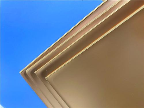
The image below shows the Rogers TMM3 copper-clad laminate material, illustrating the ceramic-filled thermoset substrate with electrodeposited copper foil cladding.
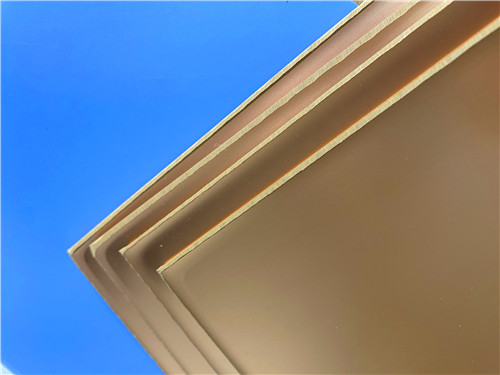
Figure 1: Rogers TMM3 Copper-Clad Laminate (CCL)
Rogers TMM3 copper-clad laminate is a versatile high-frequency material that bridges the gap between ceramic substrates and PTFE-based soft substrates. With its tightly controlled dielectric constant (3.27 +/- 0.032 process Dk, 3.45 design Dk), low dissipation factor (0.0020 at 10GHz), copper-matched CTE (15 ppm/K x/y), and thermoset resin system, TMM3 delivers reliable electrical and mechanical performance across a wide range of operating conditions. Its thermal conductivity of 0.70 W/m/K — approximately twice that of conventional PTFE/ceramic laminates — provides meaningful thermal management advantages, while its decomposition temperature of 425 degree C and lead-free process compatibility ensure robustness in modern assembly environments.
The material's compatibility with standard PWB processes, elimination of sodium napthanate treatment, and inherent wire-bonding capability make it a practical and cost-effective choice for designers seeking high-frequency performance without the manufacturing complexities of PTFE laminates. Available in thicknesses from 0.015 inch to 0.500 inch with copper claddings from 1/2 oz to 2 oz, TMM3 supports a broad spectrum of RF and microwave applications — from antennas, filters, and couplers to power amplifiers, satellite communications, and chip testers. For the featured2-layer 100mil PCB, TMM3 provides the foundational material performance that enables the product's high-frequency capabilities and long-term reliability.





Previous:
Rogers 20mil RT/duroid 6202 2-layer ENIG High-Frequency Microwave PCBNext:
2-Layer 20mil Rogers TMM13i with ENIG Finish High-Frequency Microwave Circuit BoardIf you have questions or suggestions,please leave us a message,we will reply you as soon as we can!
Categories
New Products

Wangling F4BTMS220 2-Layer DK2.2 PCB 10 mil Core with Immersion Gold

Wangling F4BTME350 10mil DK3.5 High Frequency Substrate PCB 2-Layer Immersion Gold

Wangling F4BTM300 Custom 2-layer PCB 20mil DK3.0 Substrate with Immersion Gold

Rogers 20mil RT/duroid 6202 2-layer ENIG High-Frequency Microwave PCB

Rogers 20mil AD250C PCB Pure Gold High-Frequency Antenna Circuit Board

8-Layer Hybrid RF PCB: RO4350B + TG170 FR-4 + RO4003C with RO4450F Bondply

4-Layer Rogers RO3010 Hybrid PCB Immersion Silver 2.8mm Finished Thickness

4-Layer 20mil Rogers RO3210 ISIG High-Frequency PCB with Controlled Depth Milling
This is a type of double sided RF PCB built on RT/duroid 5880 for the application of Radar Systems.
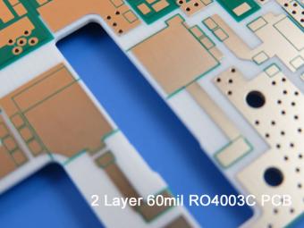
RO4003C PCBs are hydrocarbon ceramic filled laminates, not PTFE which are designed to offer superior high frequency performance.
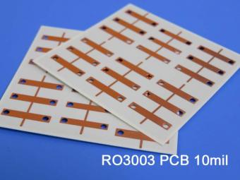
Rogers RO3003 high frequency circuit materials are ceramic-filled PTFE composites intended for use in commercial microwave and RF applications. It was designed to offer exceptional electrical and mechanical stability at competitive prices.
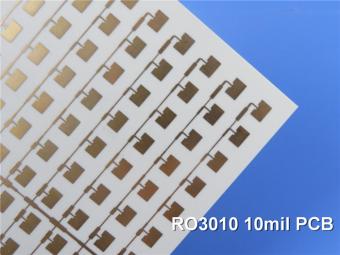
RO3010 laminates are competitively priced products with exceptional mechanical and electrical stability. This stability simplifies the design of broadband components and allows the materials to be used in a wide range of applications over a very broad range of frequencies.
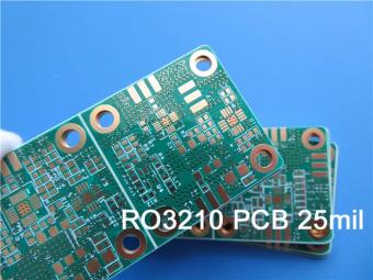
These RO3210 materials are engineered to offer exceptional electrical performance and mechanical stability. RO3210 laminates combine the surface smoothness of a non-woven PTFE laminate.
RT/duroid 6035HTC laminates are an exceptional choice for high power applications.
TC350 is designed to provide enhanced heat-transfer through “Best-In-Class” thermal conductivity, while reducing dielectric loss and insertion loss. Lower losses result in higher Amplifier and Antenna Gains/Efficiencies.
RO3035 materials exhibit a coefficient of thermal expansion(CTE) in the X and Y axis of 17 ppm/℃. This expansion coefficient is matched to that of copper, which allows the material to exhibit excellent dimensional stability.
 6-11C Shidai Jingyuan, Fuyong, Baoan, Shenzhen, Guangdong, China 518103


For inquiries about our products or pricelist, please leave to us and we will be in touch within 24 hours.
© Copyright: 2026 Shenzhen Bicheng Electronics Technology Co., Ltd.. All Rights Reserved.

IPv6 network supported


