

 Call Us Now !
Tel : +86 755 27374946
Call Us Now !
Tel : +86 755 27374946
 Order Online Now !
Email : info@bichengpcb.com
Order Online Now !
Email : info@bichengpcb.com
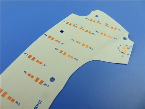
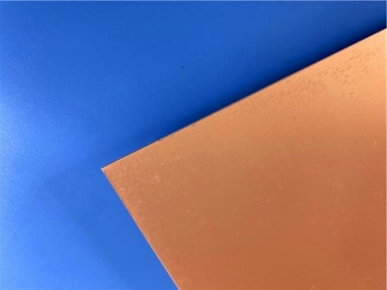
The TFA1020 PCB combines a high-Dk (10.2) PTFE-ceramic substrate, an ultra-thin 0.127 mm core, 1 oz copper construction, and a pure gold surface finish to deliver a high-performance 2-layer rigid board for microwave and millimeter-wave applications.
Item NO.:
BIC-616-v701Order(MOQ):
1-10Payment:
T/TProduct Origin:
ChinaShipping Port:
ShenzhenLead Time:
7-10 days
Wangling TFA1020 Custom 2-layer High DK PCB 0.127mm 5mil with Pure Gold
High-Frequency 2-Layer Rigid Printed Circuit Board — Technical Product Description
This article provides a comprehensive technical overview of the Wangling TFA1020 PCB, a 2-layer rigid high-frequency circuit board built on a 5mil TFA1020 PTFE-ceramic composite core with pure gold surface finish.
The first section details the PCB construction, stackup, design statistics, manufacturing capabilities, quality standards, and target applications. The second section delivers an in-depth technical knowledge base for the TFA1020 copper-clad laminate (CCL) material, covering its composition, complete data sheet, electrical performance charts, copper foil options, available form factors, and metal-base variants. Both sections are presented independently to ensure clarity and avoid content overlap.
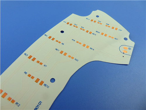
Part 1: PCB Product Description
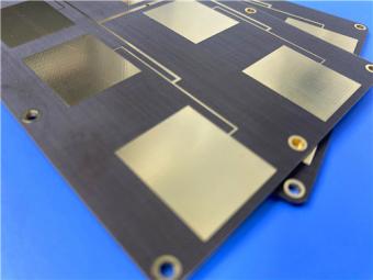
The TFA1020 PCB is a 2-layer rigid high-frequency printed circuit board engineered for demanding microwave and millimeter-wave applications. At its core lies a 0.127 mm (5 mil) TFA1020 dielectric substrate — a PTFE-ceramic composite material with a dielectric constant of 10.2 at 10 GHz — sandwiched between two 35 μm (1 oz) copper layers. The board is finished with pure gold surface treatment, delivering exceptional electrical conductivity, corrosion resistance, and long-term reliability for high-frequency signal transmission.
The high dielectric constant of 10.2 is a defining design advantage. In high-frequency circuits, the guided wavelength is inversely proportional to the square root of Dk; a Dk of 10.2 reduces the guided wavelength by approximately 69 % compared to standard FR-4 (Dk ≈ 4.3), enabling proportionally smaller resonant structures, patch antennas, and filter cavities. This size reduction is especially valuable in phased array systems where element spacing must remain below half a wavelength to avoid grating lobes, and in portable aerospace devices where board real estate is severely constrained.
The table below summarizes the complete construction specifications of the TFA1020 high frequency PCB, covering dimensional tolerances, electrical parameters, and surface treatment details.
|
Parameter |
Specification |
|
Board Dimensions |
67.4 mm × 89 mm (1 PCS), ±0.15 mm |
|
Minimum Trace / Space |
4 / 6 mils |
|
Minimum Hole Size |
0.35 mm |
|
Blind Vias |
None |
|
Finished Board Thickness |
0.25 mm |
|
Finished Cu Weight (Outer Layers) |
1 oz (1.4 mils / 35 μm) |
|
Via Plating Thickness |
20 μm |
|
Surface Finish |
Pure Gold |
|
Top Silkscreen |
No |
|
Bottom Silkscreen |
No |
|
Top Solder Mask |
No |
|
Bottom Solder Mask |
No |
|
Electrical Test |
100 % prior to shipment |
|
Quality Standard |
IPC-Class-2 |
|
Artwork Format |
Gerber RS-274-X |
|
Availability |
Worldwide |
The PCB employs a symmetric 2-layer rigid stackup centered on the TFA1020 core, with identical copper weights on both sides for balanced electrical and thermal performance.
|
Layer |
Material |
Thickness |
|
Copper Layer 1 (Top) |
Electrodeposited Copper |
35 μm (1 oz) |
|
Dielectric Core |
TFA1020 (PTFE-Ceramic Composite) |
0.127 mm (5 mil) |
|
Copper Layer 2 (Bottom) |
Electrodeposited Copper |
35 μm (1 oz) |
The Wangling board's design statistics reflect a focused, high-frequency circuit with a modest component count and minimal net complexity, characteristic of dedicated microwave or antenna modules.
|
Metric |
Count |
|
Components |
24 |
|
Total Pads |
30 |
|
Through-Hole Pads |
18 |
|
Top SMT Pads |
12 |
|
Bottom SMT Pads |
0 |
|
Vias |
11 |
|
Nets |
2 |
The pure gold surface finish is a critical differentiator for this high-frequency PCB. Unlike conventional ENIG (Electroless Nickel Immersion Gold) or HASL (Hot Air Solder Leveling) finishes, pure gold provides a direct gold-to-copper interface with no intermediate nickel layer. This eliminates the signal attenuation and skin-effect losses associated with nickel at microwave frequencies, ensuring the full benefit of the TFA1020 substrate's low-loss characteristics is realized at the conductor surface.
Gold also offers superior corrosion resistance — essential for boards deployed in humid or aerospace environments — excellent solderability for repeated assembly and rework cycles, and stable contact resistance over the product lifetime. For aerospace, defense, and satellite applications where long-term reliability is non-negotiable, the pure gold finish provides a level of assurance that conventional surface treatments cannot match.
Quality is embedded at every stage of production. The manufacturing process adheres to IPC-Class-2 standards, with incoming material inspection, in-process quality checks at lamination, drilling, plating, and etching stages, and a final 100 % electrical test.
Each board is verified for net continuity and insulation resistance before shipment. The PTFE-ceramic substrate requires specialized lamination profiles and drilling parameters compared to conventional FR-4, and our process is qualified for these high-frequency materials to ensure consistent via wall quality and registration accuracy. The use of Gerber RS-274-X artwork ensures universal CAM compatibility and precise fabrication. The product is available for worldwide shipment, supporting global customers in aerospace, defense, telecommunications, and research sectors.
The 2-layer TFA1020 PCB is ideally suited for the following high-frequency application domains:
· Aerospace and avionics equipment, including in-cabin and space-borne systems
· Microwave circuits and high-frequency antennas, including phase-sensitive antennas
· Early warning radar and airborne radar systems
· Phased array antennas and beamforming networks
· Satellite communications and navigation systems
· High-power amplifiers operating at microwave and millimeter-wave frequencies
The TFA1020 PCB combines a high-Dk (10.2) PTFE-ceramic substrate, an ultra-thin 0.127 mm core, 1 oz copper construction, and a pure gold surface finish to deliver a high-performance 2-layer rigid board for microwave and millimeter-wave applications. Its fine-line capability (4/6 mils), 100 % electrical testing, and IPC-Class-2 quality assurance ensure reliable performance in demanding environments.
The deliberate absence of solder mask and silkscreen further optimizes the board for uncompromised high-frequency signal integrity. For design engineers seeking a compact, high-Dk, low-loss PCB solution for aerospace, radar, satellite communication, or power amplifier applications, the TFA1020 PCB offers a compelling combination of advanced material performance and manufacturing precision.
Part 2: CCL Material Knowledge — TFA1020
TFA1020 is a high-dielectric-constant (Dk = 10.2) PTFE-ceramic composite copper-clad laminate manufactured by Taizhou Wangling Insulation Materials Factory. It belongs to the TFAPCB substrateseries, which encompasses four dielectric constant options to cover a broad design spectrum: TFA294 (Dk = 2.94), TFA300 (Dk = 3.0), TFA615 (Dk = 6.15), and TFA1020 (Dk = 10.2). The TFA1020 grade is specifically engineered for applications requiring a high dielectric constant combined with ultra-low dielectric loss — such as miniaturized patch antennas, phase shifters, directional couplers, and high-frequency filter circuits where the high Dk enables significant size reduction.
Unlike conventional FR-4 or standard high-frequency laminates that use glass fiber cloth impregnated with resin, the TFA series employs a fundamentally different manufacturing approach. The dielectric layer consists of PTFE (polytetrafluoroethylene) resin uniformly mixed with a large quantity of special nano-ceramic particles. This mixture is formed into prepreg sheets using a proprietary new process, followed by lamination under specialized pressing conditions to achieve the final copper-clad laminate.
The absence of glass fiber cloth eliminates the so-called "fiberglass effect" — the local variation in dielectric constant caused by the weave pattern of glass fibers — which is particularly critical at high frequencies where the signal wavelength approaches the dimensions of the weave structure. This results in excellent frequency stability, minimal dielectric loss at the same Dk level, and near-isotropic electrical properties across the X, Y, and Z axes. The material also exhibits a low thermal expansion coefficient equivalent to copper foil (16 ppm/°C in X/Y), ensuring reliable via plating adhesion and dimensional stability under thermal cycling.
· Dielectric constant tolerance of ±0.20, with excellent batch-to-batch consistency for repeatable designs
· Industry-leading low dielectric loss at the 10.2 Dk level: 0.0015 at 10 GHz, 0.0017 at 20 GHz
· Usable frequency up to 77 GHz, supporting millimeter-wave and automotive radar applications
· Stable frequency and phase performance across the full operating range of -55 °C to +150 °C
· Excellent radiation resistance, maintaining stable dielectric and physical properties after irradiation exposure
· Low outgassing performance, meeting aerospace vacuum outgassing requirements for space applications
· CTE of 16 ppm/°C (X/Y axis) — matched to copper foil — ensuring via reliability and dimensional thermal stability
· Low moisture absorption of 0.015 %, guaranteeing electrical stability in humid environments
· UL 94 V-0 flammability rating for fire safety compliance
· Long-term operating temperature range: -55 °C to +260 °C
The following table provides the complete technical specifications for TFA1020. All values are typical measurements tested per IPC-TM-650, GB/T 12636-1990 (stripline method), and GB/T 4722-2017 standards. The dielectric constant (typical value) is measured in the Z-direction of the material; the design value is measured using the 50 Ω microstrip line method.
|
Property |
Test Condition |
Unit |
TFA1020 Value |
|
Dielectric Constant (Typical) |
10 GHz |
— |
10.20 |
|
Dielectric Constant (Design) |
10 GHz |
— |
10.7 |
|
Dk Tolerance |
— |
— |
±0.20 |
|
Dissipation Factor (Typical) |
10 GHz |
— |
0.0015 |
|
Dissipation Factor (Typical) |
20 GHz |
— |
0.0017 |
|
TCDK (Temp. Coeff. of Dk) |
-55 °C ~ +150 °C |
ppm/°C |
-340 |
|
Peel Strength |
1 oz RTF Copper Foil |
N/mm |
>1.6 |
|
Volume Resistivity |
Normal condition |
MΩ·cm |
≥5×10⁷ |
|
Surface Resistivity |
Normal condition |
MΩ |
≥5×10⁷ |
|
Electric Strength (Z-direction) |
5 kW, 500 V/s |
kV/mm |
>30 |
|
Breakdown Voltage (XY-direction) |
5 kW, 500 V/s |
kV |
>25 |
|
CTE (X, Y direction) |
-55 °C ~ +288 °C |
ppm/°C |
16, 16 |
|
CTE (Z direction) |
-55 °C ~ +288 °C |
ppm/°C |
30 |
|
Thermal Stress |
260 °C, 10 s, 3 cycles |
— |
No delamination |
|
Moisture Absorption |
20±2 °C, 24 h |
% |
0.015 |
|
Density |
Room temperature |
g/cm³ |
3.0 |
|
Long-term Operating Temp. |
High/low temp. chamber |
°C |
-55 ~ +260 |
|
Thermal Conductivity |
Z-direction |
W/(m·K) |
0.88 |
|
Flammability |
— |
UL-94 |
V-0 |
|
TD (Decomposition Temp.) |
Onset |
°C |
505 |
|
Material Composition |
— |
— |
PTFE + Ceramic |
TFA series laminates come standard with RTF (Reverse Treated Foil) low-roughness copper foil, which reduces conductor loss at high frequencies while maintaining excellent peel strength (>1.6 N/mm for 1 oz RTF copper). Available standard copper foil thicknesses include 0.5 oz (0.018 mm) and 1 oz (0.035 mm), with other thicknesses available upon custom request.
Additional copper foil and substrate configuration options include:
· Rolled Annealed (RA) copper foil for further improved high-frequency conductor performance
· 50 Ω embedded resistor copper foil: Ni-P alloy resistive layer, 0.2 μm thickness, sheet resistance 50±5 Ω/square (available for TFA294 and TFA300 grades)
· Copper base (TFA-CU) or aluminum base (TFA-AL) for enhanced thermal management and electromagnetic shielding
Standard panel sizes (custom sizes available upon request):
· 305 mm × 460 mm (12" × 18")
· 460 mm × 610 mm (18" × 24")
The TFA series offers a minimum dielectric thickness of 0.127 mm (5 mil) — the thinnest in the series — with thicknesses available in multiples of 0.127 mm. The full standard range spans from 0.127 mm (5 mil) to 6.35 mm (250 mil), with thickness tolerances ranging from ±0.0127 mm (0.5 mil) for thin substrates to ±0.32 mm (12.6 mil) for the thickest options. The table below summarizes the standard available thicknesses and corresponding tolerances.
|
Dielectric Thickness |
Tolerance |
|
0.127 mm (5.0 mil) |
±0.0127 mm (0.5 mil) |
|
0.254 mm (10 mil) |
±0.02 mm (1.0 mil) |
|
0.508 mm (20 mil) |
±0.03 mm (1.19 mil) |
|
0.635 mm (25 mil) |
±0.03 mm (1.58 mil) |
|
0.762 mm (30 mil) |
±0.04 mm (1.58 mil) |
|
1.016 mm (40 mil) |
±0.05 mm (2.0 mil) |
|
1.270 mm (50 mil) |
±0.05 mm (2.0 mil) |
|
1.524 mm (60 mil) |
±0.07 mm (2.5 mil) |
|
1.905 mm (75 mil) |
±0.09 mm (3.5 mil) |
|
2.03 mm (80 mil) |
±0.09 mm (3.5 mil) |
|
2.54 mm (100 mil) |
±0.13 mm (5.0 mil) |
|
3.175 mm (125 mil) |
±0.20 mm (8.0 mil) |
|
3.81 mm (150 mil) |
±0.25 mm (10.0 mil) |
|
4.06 mm (160 mil) |
±0.25 mm (10.0 mil) |
|
5.08 mm (200 mil) |
±0.25 mm (10.0 mil) |
|
6.35 mm (250 mil) |
±0.32 mm (12.6 mil) |
For applications requiring enhanced thermal management or electromagnetic shielding, TFA series laminates are available with aluminum or copper metal bases. These variants feature a dielectric layer with copper foil on one side and a metal base (aluminum or copper) bonded to the other side, providing both a heat-spreading path and a ground/shielding plane. The model nomenclature is TFA-AL for aluminum base and TFA-CU for copper base (e.g., TFA1020-AL, TFA1020-CU).
|
Parameter |
TFA-CU (Copper Base) |
TFA-AL (Aluminum Base) |
|
Metal Base Material |
Purple Copper / Brass |
Aluminum |
|
Density |
8.9 g/cm³ |
2.7 g/cm³ |
|
Thermal Conductivity |
380 W/(m·K) |
180 W/(m·K) |
|
CTE (X/Y) |
17 ppm/°C |
24 ppm/°C |
|
Available Metal Base Thickness |
0.48, 0.98, 1.48, 1.98, 2.98, 3.98 mm |
0.48, 0.98, 1.48, 1.98, 2.98, 3.98 mm |
|
Thickness Tolerance |
+0.02 / -0.05 mm |
+0.02 / -0.05 mm |
|
Available Panel Size |
460×610 mm, 460×305 mm |
460×610 mm, 460×305 mm |
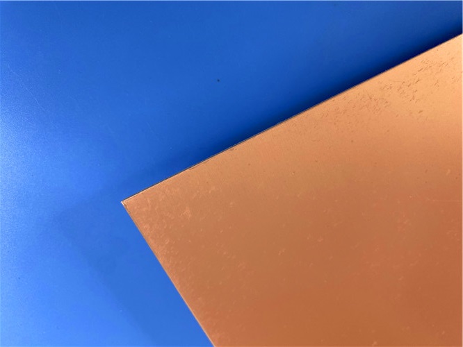
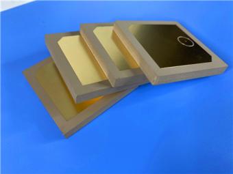
Figure 3: TFA1020 PTFE-Ceramic Composite Copper-Clad Laminate (as-manufactured panel)
TFA1020 is a high-Dk (10.2), ultra-low-loss PTFE-ceramic composite laminate that offers a competitive domestic alternative to imported high-frequency materials. Its glass-fiber-free construction eliminates the fiberglass effect, delivering near-isotropic electrical properties, excellent frequency stability up to 77 GHz, and a predictable TCDK of -340 ppm/°C. With a CTE matched to copper foil (16 ppm/°C in X/Y), ultra-low moisture absorption (0.015 %), UL 94 V-0 rating, decomposition temperature of 505 °C, and long-term operating temperatures up to 260 °C, TFA1020 is well-suited for the most demanding aerospace, radar, satellite communication, and high-power amplifier applications.
The availability of multiple copper foil options (RTF standard, RA, embedded resistor), metal base variants (aluminum and copper with thermal conductivity up to 380 W/m·K), and a wide range of dielectric thicknesses (from 0.127 mm to 6.35 mm) provides design engineers with the flexibility needed to optimize their high-frequency circuit layouts for performance, thermal management, and form factor. Combined with its documented batch-to-batch consistency and full compliance with IPC and national test standards, TFA1020 represents a reliable, high-performance material choice for next-generation microwave and millimeter-wave electronic systems.





Previous:
High-Frequency 2-Layer PCB on 59mil Wangling TP440 Thermoplastic Dielectric Immersion GoldNext:
Wangling F4BM245 PCB 20mil Laminate 2-Layer Immersion Gold No Solder Mask SilkscreenIf you have questions or suggestions,please leave us a message,we will reply you as soon as we can!
Categories
New Products
Wangling TP2200 PCB 0.8mm Substrate Immersion Gold 2-Layer High-Dk (Dk 22) RF Board
Rogers TMM10 PCB 5.08mm Core ENIG 2-Layer High-Dk Microwave Board
Taconic TLX-8 PCB 50mil ENIG 2-Layer High-Frequency RF Circuit Board
Wangling TF440 25mil DK4.4 Laminate Immersion Gold 2-Layer Copper-filling Vias PCB
RO4360G2 Rogers 12mil ENEPIG 2-Layer DK6.15 High Frequency Custom PCB

Wangling F4BTMS220 2-Layer DK2.2 PCB 10 mil Core with Immersion Gold

Wangling F4BTME350 10mil DK3.5 High Frequency Substrate PCB 2-Layer Immersion Gold

Wangling F4BTM300 Custom 2-layer PCB 20mil DK3.0 Substrate with Immersion Gold
Polytetrafluoroethylene (Short for PTFE), commonly known as "plastic king ", is a polymer compound made of tetrafluoroethylene by polymerization. It has excellent chemical stability, corrosion resistance, sealing, high lubrication and non-viscosity, electrical insulation and good aging resistance.
Rogers TMM4 thermoset microwave material is ceramic, hydrocarbon, thermoset polymer composite designed for high plated-through-hole reliability stripline and microstrip applications.
Taconic TLY laminates are a type of low loss laminates. They are manufactured with very light weight woven fiberglass and are more dimensionally stable than chopped fiber reinforced PTFE composites.
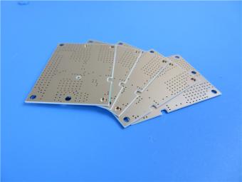
RO3203 laminates combine the surface smoothness of a non-woven PTFE laminate, for finer line etching tolerances, with the rigidity of a woven-glass PTFE laminate. These materials can be fabricated into printed circuit boards using
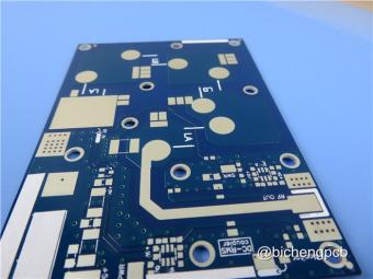
This type of immersion silver RF PCB is made on one of Taconic’s ORCER family material: RF-45.
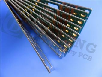
Rogers’ TMM10 thermoset microwave materials are ceramic, hydrocarbon, thermoset polymer composites designed for high plated-thru-hole reliability stripline and microstrip applications.
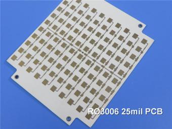
Rogers RO3006 was designed to offer exceptional electrical and mechanical stability at competitive prices.
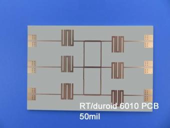
RT/duroid 6010LM microwave laminates feature ease of fabrication and stability in use. This property results in the possibility of mass production and reducing the cost of goods.
 6-11C Shidai Jingyuan, Fuyong, Baoan, Shenzhen, Guangdong, China 518103


For inquiries about our products or pricelist, please leave to us and we will be in touch within 24 hours.
© Copyright: 2026 Shenzhen Bicheng Electronics Technology Co., Ltd.. All Rights Reserved.

IPv6 network supported


