

 Call Us Now !
Tel : +86 755 27374946
Call Us Now !
Tel : +86 755 27374946
 Order Online Now !
Email : info@bichengpcb.com
Order Online Now !
Email : info@bichengpcb.com

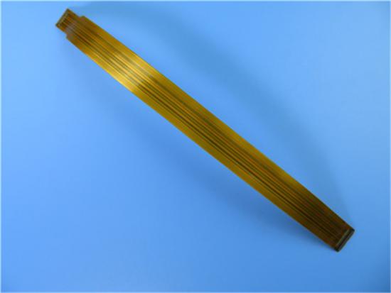

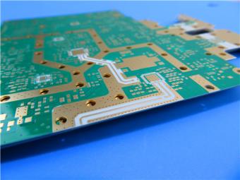
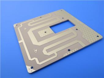
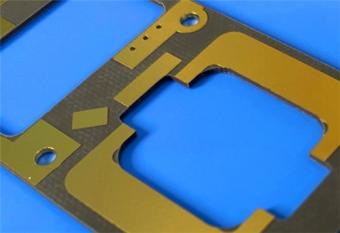
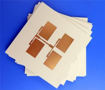
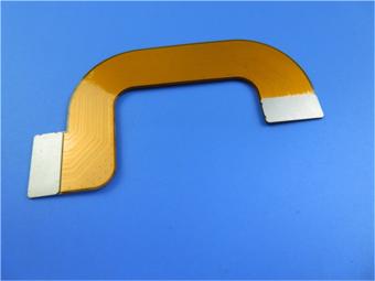
This type of flexible circuit is 4-layer
structure built on polyimide (PI) for the application of wireless router, 1oz
copper each layer.
Item NO.:
BIC-265-v68.0Order(MOQ):
1-10Payment:
T/TProduct Origin:
ChinaShipping Port:
ShenzhenLead Time:
7-10 daysMultilayer Flexible Printed Circuit (FPC) Multi-layer Flexible PCB Board
(FPC’s are custom-made products, the picture and parameters shown are just for reference)
General description:
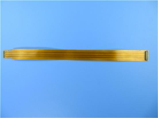
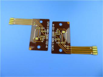
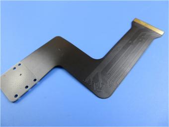
The base laminate is from Shengyi. Coated by yellow covering layer, immersion gold is plated on pads. A connector is designed at both ends. It’s fabricated per IPC 6012 Class 2 using supplied Gerber data.
Parameter and data sheet:
| Size of Flexible PCB | 300.5X 25.5mm |
| Number of Layers | 4 |
| Board Type | Flexible circuits |
| Board Thickness | 0.30mm |
| Board Material | Polyimide (PI) 25µm |
| Board Material Supplier | Shengyi |
| Tg Value of Board Material | 60℃ |
| PTH Cu thickness | ≥20 µm |
| Inner Iayer Cu thicknes | 35 µm |
| Surface Cu thickness | 35 µm |
| Coverlay Colour | Yellow |
| Number of Coverlay | 2 |
| Thickness of Coverlay | 25 µm |
| Stiffener Material | NO |
| Stiffener Thickness | N/A |
| Type of Silkscreen Ink | NO |
| Supplier of Silkscreen | N/A |
| Color of Silkscreen | N/A |
| Number of Silkscreen | N/A |
| Peeling test of Coverlay | No peelable |
| Legend Adhesion | 3M 90℃No peeling after Min. 3 times test |
| Surface Finish | Immersion Gold |
| Thickness of Nickle/Gold | Au: 0.03µm(Min.); Ni 2-4µm |
| RoHS Required | Yes |
| Famability | 94-V0 |
| Thermal Shock Test | Pass, -25℃±125℃, 1000 cycles. |
| Thermal Stress | Pass, 300±5℃,10 seconds, 3 cycles. No delamination, no blistering. |
| Function | 100% Pass electrical test |
| Workmanship | Compliance with IPC-A-600H & IPC-6013C Class 2 |

Features and benefits:
Excellent flexibility
Reducing the volume
Weight reduction
Consistency of assembly
Increased reliability
Material optionality
Low cost
Continuity of processing
Diversified shipping method
Engineering design prevents problems from occurring in pre production.
Applications:
Laser head FPC, medical equipment controller, Tablet antenna soft board
Multilayer Flexible Circuits:
For the most part, manufacture of multilayer flexible circuits is based upon processes of single sided flexible PCB and double sided PTH flexible PCB. Both types evolve from the conventional covercoated double-sided flexible circuits that are bonded together. For a number of reasons, it is not recommended to combine too many flexible circuits into a multilayer flexible circuit.
Materials and Thicknesses of Multilayer FPC
It is common practice to use the materials listed below.
Dielectric Substrates
50 µm (2 mil) polyimide because of its higher stability and easier handling compared with 25 µm (1 mil) polyimide.
Copper Foil
35 µm (1 oz.) copper foil, provided this thickness is compatible with the current carrying requirements of the finished circuit.
Covercoat
25 µm (1 mil) polyimide for a 35 µm (1.4 mil) thick copper foil, since it ensures a better encapsulation of the conductors than a 50 µm (2 mil) polyimide.
25 µm (1 mil) acrylic adhesive for achieving a good encapsulation and a low-flow lamination. Too much acrylic adhesive leads to reliability problems, e.g. barrel cracks, foil cracks, and a too deep etchback.
Outer Layers
Outer layers should not be provided with any circuitry (conductors) on the bonding side because of the risk of air entrapment at the interface.
Bonding Materials
When using covercoated flexible circuits as inner layers, the circuits and the rigid parts are bonded together by means of sheet adhesives.
Processes:
A simplified flow diagram is shown below.

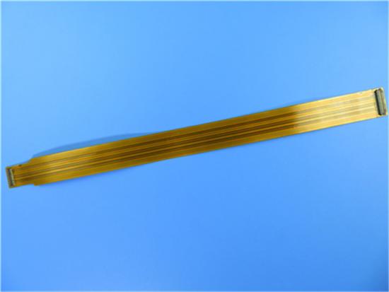
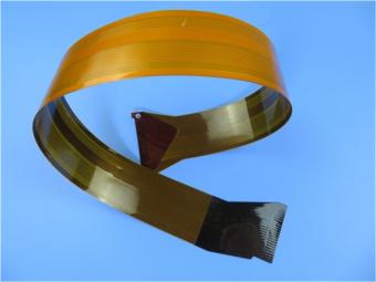
More Displays of Multi-layer FPC:


BICHENG MAIN COURIERS:

Previous:
Heavy Copper Flexible PCB Built On Polyimide with 2 oz CopperNext:
Flexible Printed Circuit FPC on Polyimide with 2 Meters LongIf you have questions or suggestions,please leave us a message,we will reply you as soon as we can!
Categories
New Products

2-Layer 20mil FSD1020T ENIG High-Frequency PCB with Via Resin Plugged and Capped

4-Layer F4BM265+S1000-2M Material Hyrbid PCB with Blind Via Impedance Control & ENIG

4-Layer Wangling WL-CT338 + FR4 Hybrid PCB ENIG Green Solder Mask White Silkscreen

6-layer Isola 370HR High-Tg FR-4 PCB 2μ" ENIG Impedance Controlled
6-Layer RO4003C + FR4 Mixed Dielectric PCB with Hard Gold Plating Blind Via
30mil Taconic CER-10 2-layer Immersion Silver DK10 High Frequency Laminate PCB
31mil Rogers RT/duroid 5880 Double-sided Bare Copper ENIG Finished PCB
Wangling TFA294 Laminate 40mil Immersion Silver No Solder Mask Silkscreen Custom PCB
Flexible Printed Circuit Board (FPC) is referred to as "soft board". In the industry, FPC is a printed circuit board made of flexible insulating substrate (mainly polyimide or polyester film), which has many advantages that rigid printed circuit boards do not have.
It’s a 2 layer flex board at 0.15mm thick. It contains yellow coverlay (solder mask) and without silkscreen on entire board, and immersion gold is applied on pads.

This is a type of flexible printed circuit for the application of Surveillance System. It’s a single layer FPC at 0.15mm thick.
This is a type of single layer flexible printed circuit for the application of Wireless Dongle, 0.2mm thick.
It’s fabricated per IPC 6012 Class 2 using supplied Gerber data. Stainless steel as stiffener is applied on the two ends.
This is a type of flexible printed circuit for the application of PLC Programing.

This is a type of dual layer flexible circuit built on PET substrate, 1oz copper weight on each layer.
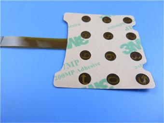
This type of flexible printed circuit is for the application of calculator keypad. It’s a single layer FPC at 0.15mm thick.
 6-11C Shidai Jingyuan, Fuyong, Baoan, Shenzhen, Guangdong, China 518103


For inquiries about our products or pricelist, please leave to us and we will be in touch within 24 hours.
© Copyright: 2026 Shenzhen Bicheng Electronics Technology Co., Ltd.. All Rights Reserved.

IPv6 network supported


