

 Call Us Now !
Tel : +86 755 27374946
Call Us Now !
Tel : +86 755 27374946
 Order Online Now !
Email : info@bichengpcb.com
Order Online Now !
Email : info@bichengpcb.com
RF-35TC High frequency PCB exhibits a low dissipation factor while also providing high thermal conductivity.
Item NO.:
BIC-221-v245.0Order(MOQ):
1-10Payment:
T/TProduct Origin:
ChinaShipping Port:
ShenzhenLead Time:
7-10 days
RF-35TCPCB 30mil Taconic SubstrateHigh FrequencyBoard
Introduction
RF-35TC is a fiberglass laminate filled with ceramic and based on PTFE. It possesses the remarkable ability to resist oxidation, yellowing, and upward drift in dielectric constant and dissipation factor.
RF-35TC High frequency PCB exhibits a low dissipation factor while also providing high thermal conductivity. This allows for effective heat diffusion from transmission lines and surface mount components like capacitors.
RF-35TC Typical Properties
To begin, let's delve into the dielectric properties of RF-35TC. At 10 GHz, it has a dielectric constant (DK) of 3.5, which is lower compared to most high frequency PCBs. Additionally, its temperature coefficient of dielectric constant (TCDk) remains consistent at 24 ppm within the temperature range of -30 to 120℃, thus guaranteeing stability.
Moving on to the electrical properties of RF-35TC PCB, it has a low dissipation factor (Df) of 0.0011 at 10 GHz. This indicates minimal signal loss and high signal integrity, unlike RT/duroid 6035HTC with a Df of 0.0013, TC600 with a Df of 0.0017, and TC350 with a Df of 0.002. The RF-35TC material also boasts impressive dielectric breakdown and dielectric strength values of 56.7 kV and 570 V/mil (22,441 V/mm) respectively.

More typical propertiesRF-35TCas follows:
|
RF-35TC TYPICAL VALUES |
|||||
|
Property |
Test Method |
Unit |
Value |
Unit |
Value |
|
DK @10 GHz |
IPC-650 2.5.5.5.1(modified) |
|
3.5 |
|
3.5 |
|
Tck(-30 to 120℃) |
IPC-650 2.5.5.5.1(modified) |
ppm |
24 |
ppm |
24 |
|
Df @10 GHz |
IPC-650 2.5.5.5.1(modified) |
|
0.0011 |
|
0.0011 |
|
Dielectric Breakdown |
IPC-650 2.5.6(in-Plane,Two Pins in Oil) |
kV |
56.7 |
kV |
56.7 |
|
Dielectric Strength |
ASTM D 149(Through Plane) |
V/mil |
570 |
V/mm |
22,441 |
|
Arc Resistance |
IPC-650 2.5.1 |
Seconds |
304 |
Seconds |
304 |
|
Moisture Absorption |
IPC-650 2.6.2.1 |
% |
0.05 |
% |
0.05 |
|
Flexural Strength(MD) |
ASTM D 790/IPC-650 2.4.4 |
psi |
12,900 |
N/mm2 |
88.94 |
|
Flexural Strength(CD) |
ASTM D 790/IPC-650 2.4.4 |
psi |
11,700 |
N/mm2 |
80.67 |
|
Tensile Strength(MD) |
ASTM D 3039/IPC-TM-650 2.4.19 |
psi |
9,020 |
N/mm2 |
62.19 |
|
Tensile Strength(CD) |
ASTM D 3039/IPC-TM-650 2.4.19 |
psi |
7,740 |
N/mm2 |
53.37 |
|
Elongation at Break(MD) |
ASTM D 3039/IPC-TM-650 2.4.19 |
% |
1.89 |
N/mm |
1.89 |
|
Elongation at Break(CD) |
ASTM D 3039/IPC-TM-650 2.4.19 |
% |
1.7 |
% |
1.7 |
|
Young's Modulus(MD) |
ASTM D 3039/IPC-TM-650 2.4.19 |
psi |
667,000 |
N/mm2 |
4,599 |
|
Young's Modulus(CD) |
ASTM D 3039/IPC-TM-650 2.4.19 |
psi |
637,000 |
N/mm2 |
4,392 |
|
Poisson's Ratio(MD) |
ASTM D 3039/IPC-TM-650 2.4.19 |
|
0.18 |
|
0.18 |
|
Poisson's Ratio(CD) |
ASTM D 3039/IPC-TM-650 2.4.19 |
|
0.23 |
|
0.18 |
|
Compressive Modulus |
ASTM D 695(23℃) |
psi |
560,000 |
N/mm2 |
3,861 |
|
Flexural Strength(MD) |
ASTM D 790/IPC-650 2.4.4 |
psi |
1.46 x 10⁶ |
N/mm2 |
10,309 |
|
Flexural Strength(CD) |
ASTM D 790/IPC-650 2.4.4 |
psi |
1.50 x 10⁶ |
N/mm2 |
10,076 |
|
Peel Stength(½ oz.CVH) |
IPC-650 2.4.8(Thermal Stress.) |
Ibs./inch |
7 |
g/cm3 |
1.25 |
|
Thermal Conductivity(Unclad,125℃) |
ASTM F433(Guarded Heat Flow) |
W/(mK) |
0.6 |
W/(mK) |
0.6 |
|
Thermal Conductivity(C1/C1,125℃) |
ASTM F433(Guarded Heat Flow) |
W/(mK) |
0.92 |
W/(mK) |
0.92 |
|
Thermal Conductivity(CH/CH,125℃) |
ASTM F433(Guarded Heat Flow) |
W/(mK) |
0.87 |
W/(mK) |
0.87 |
|
Dimensional Stability(MD) |
IPC-650-2.4.39 Sec.5.4(After Etch) |
mils/in. |
0.23 |
mm/M |
0.23 |
|
Dimensional Stability(CD) |
IPC-650-2.4.39 Sec.5.4(After Etch) |
mils/in. |
0.64 |
mm/M |
0.64 |
|
Dimensional Stability(MD) |
IPC-650-2.4.39 Sec.5.5(Thermal Stress.) |
mils/in. |
-0.04 |
mm/M |
-0.04 |
|
Dimensional Stability(CD) |
IPC-650-2.4.39 Sec.5.5(Thermal Stress.) |
mils/in. |
0.46 |
mm/M |
0.46 |
|
Surface Resistivity |
IPC-650 2.5.17.1(after elevated temp.) |
Mohms |
8.33 x 10⁷ |
Mohms |
8.33 x 10⁷ |
|
Surface Resistivity |
IPC-650 2.5.17.1(after humidity) |
Mohms |
6.42 x 10⁷ |
Mohms |
6.42 x 10⁷ |
|
Volume Resistivity |
IPC-650 2.5.17.1(after elevated temp.) |
Mohms/cm |
5.19 x 10⁸ |
Mohms/cm |
5.19 x 10⁸ |
|
Volume Resistivity |
IPC-650 2.5.17.1(after humidity) |
Mohms/cm |
2.91 x 10⁸ |
Mohms/cm |
2.91 x 10⁸ |
|
CTE(X axis)(25-260℃) |
IPC-650 2.4.41/ASTM D 3386 |
ppm/℃ |
11 |
ppm/℃ |
11 |
|
CTE(Y axis)(25-260℃) |
IPC-650 2.4.41/ASTM D 3386 |
ppm/℃ |
13 |
ppm/℃ |
13 |
|
CTE(Z axis)(25-260℃) |
IPC-650 2.4.41/ASTM D 3386 |
ppm/℃ |
34 |
ppm/℃ |
34 |
|
Density |
ASTM D 792 |
g/cm3 |
2.35 |
g/cm3 |
2.35 |
|
Hardness |
ASTM D 2240(Shore D) |
|
79.1 |
|
79.1 |
|
Strain at Break(MD) |
ASTM D 790/IPC-650 2.4.4 |
% |
0.014 |
% |
0.014 |
|
Strain at Break(CD) |
ASTM D 790/IPC-650 2.4.4 |
% |
0.013 |
% |
0.013 |
|
Specific Heat |
ASTM E 1269-05,E 967-08,E968-02 |
j/(g℃) |
0.94 |
j/(g℃) |
0.94 |
|
Td(2% Weight Loss) |
IPC-650 2.4.24.6/TGA |
oF |
788 |
℃ |
420 |
|
Td(5% Weight Loss) |
IPC-650 2.4.24.6/TGA |
oF |
817 |
℃ |
436 |
RF-35TC PCB Capability
Now, let's take a look at our PCB capabilities using RF-35TC material.
|
PCB material: |
PTFE based Ceramic filled Fiberglass |
|
Designation: |
RF-35TC |
|
Dielectric constant: |
3.50 @ 10GHz |
|
|
|
|
Layer count: |
1-layer, 2-layer, Multi-layer, Hybrid type |
|
Dielectric thickness: |
5mil (0.127mm), 10mil (0.254mm), 20mil (0.508mm), 30mil (0.762mm), 60mil (1.524mm) |
|
Copper weight: |
1oz, 2oz |
|
Solder mask: |
Green, Black, Blue, Yellow, White etc. |
|
PCB size: |
≤400mm X 500mm |
|
Surface finish: |
Immersion gold, HASL, Immersion silver, Immersion tin, Bare copper, OSP, Pure gold, ENEPIG etc. |
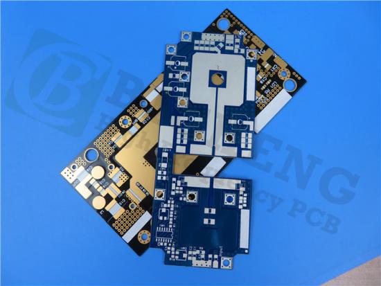
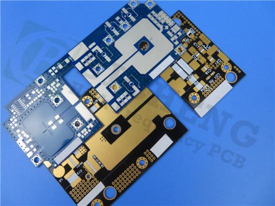
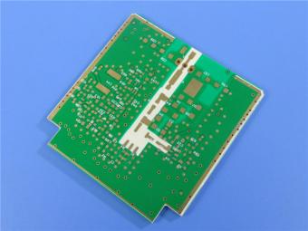
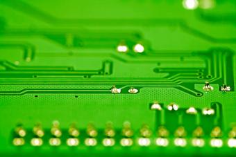
A Piece of RF-35TC PCB
RF-35TC PCBs have a basic color of brown and gray.There is a 30mil RF-35TC PCB with immersion gold and black solder mask, which is commonly used for filters.
The applications of Taconic RF-35TC PCBs in couplers, antennas, power amplifiers, and satellite equipment among others.
Conclusion
When measuring thermal conductivity, it is important to consider various techniques. Thermal conductivity measured on an unclad laminate provides the true value of the material's thermal conductivity. Measurements on a copper clad laminate (CCL) typically yield higher values due to the reduced thermal resistance at the interface between the laminate and measuring equipment. RF-35TC 30mil material PCB offers superior heat dissipation performance, whether measured with or without copper cladding.


Previous:
RT/duroid 6006 PCB Rogers 6006 50mil Material High Frequency Printed Circuit BoardsNext:
RO4830 High Frequency PCB Built on 9.4mil 0.239mm Substrates with Double Sided Copper and Immersion GoldIf you have questions or suggestions,please leave us a message,we will reply you as soon as we can!
Categories
New Products

12-layer TG200 TU-872 SLK High-Speed FR4 1.68mm PCB with ENIG Impedance Control

12-Layer RO4350B + RO3010 3.14mm Hybrid PCB Nickel-Free EPIG Surface Finish Blind Via
8-Layer Hybrid PCB RO4003C + S1000-2M FR4 with ENIG Surface Finish Blind Via
6-Layer Isola Astra MT77 PCB with Blind Via & Resin Plug Immersion Silver Finish

2-Layer 20mil FSD1020T ENIG High-Frequency PCB with Via Resin Plugged and Capped

4-Layer F4BM265+S1000-2M Material Hyrbid PCB with Blind Via Impedance Control & ENIG

4-Layer Wangling WL-CT338 + FR4 Hybrid PCB ENIG Green Solder Mask White Silkscreen

6-layer Isola 370HR High-Tg FR-4 PCB 2μ" ENIG Impedance Controlled

RF-10 25mil Taconic PCB Materials stands out as a high-performance solution for RF applications. Its exceptional electrical properties, dimensional stability, thermal conductivity, and adhesion characteristics make it an ideal choice for demanding applications.
The PCB has a 4-layer hybrid stackup with a 0.5oz+plating ground layer, two 1oz ground layers, and a 0.5oz+plating signal layer.
The dimensions of the board are 55.00 x 26.00 mm, with a tolerance of +/- 0.15mm. The board has 16 components, 26 total pads, 9 through-hole pads, 10 top SMT pads, 7 bottom SMT pads, 77 vias, and 82 nets.
Rogers RO4003C PCB is an innovative and advanced circuit board that is made with high-quality materials.
The RO4350B PCB offers a range of benefits that make it an ideal choice for high-frequency applications. Its low dielectric loss and high thermal conductivity make it perfect for high-frequency applications such as RF and microwave circuits.
Bicheng PCB Ships High-Quality PCBs with Shengyi Tg150 ℃ S1000H Material and Advanced Stackup
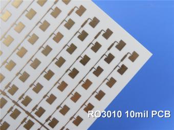
Rogers RO3010 PCB is ideal for a wide range of high-frequency applications, including power amplifiers, filters, couplers, and antennas.
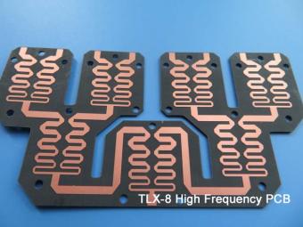
TLX-8 features low dielectric loss, low moisture absorption, and excellent thermal stability, making it ideal for high-frequency and high-speed applications. It has a low dissipation factor, which helps to minimize signal loss and distortion.
 6-11C Shidai Jingyuan, Fuyong, Baoan, Shenzhen, Guangdong, China 518103


For inquiries about our products or pricelist, please leave to us and we will be in touch within 24 hours.
© Copyright: 2026 Shenzhen Bicheng Electronics Technology Co., Ltd.. All Rights Reserved.

IPv6 network supported


