

 Call Us Now !
Tel : +86 755 27374946
Call Us Now !
Tel : +86 755 27374946
 Order Online Now !
Email : info@bichengpcb.com
Order Online Now !
Email : info@bichengpcb.com
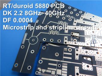
This 30mil Taconic PCB provides consistent performance, durability, and quality for mission‑critical RF systems, making it an excellent choice for industrial, communication, aerospace, and marine applications requiring superior high‑frequency performance.
Item NO.:
BIC-510-v595.0Order(MOQ):
1-10Payment:
T/TProduct Origin:
ChinaShipping Port:
ShenzhenLead Time:
7-10 days
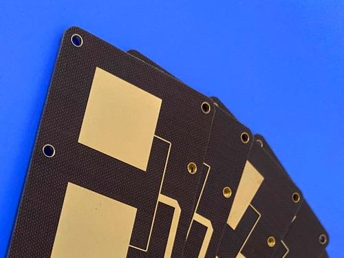
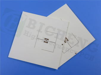
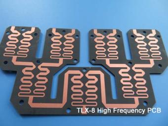
Taconic 2-Layer TLX-8 0.762mm 30mil Immersion Gold High Frequency Bare Copper PCB
This high‑performance double‑sided rigid printed circuit board is purpose‑engineered for demanding radio‑frequency and microwave applications, combining the proven stability of TLX-8 substrate with tight manufacturing control and reliable electrical performance. Unlike general‑purpose FR‑4 boards, this Taconic High Frequency PCB is optimized for low signal loss, stable dielectric properties, and long‑term durability in challenging operating environments, making it a preferred choice for professional RF systems, communication components, and high‑reliability microwave assemblies. Every production step follows strict industrial standards, from material selection and layer formation to final electrical verification, ensuring consistent quality and performance for mission‑critical end products.
PCB Construction Details
The following table summarizes the key structural and processing specifications of the TLX-8 PCB, defining its physical form, material composition, surface treatment, and quality assurance measures.
|
Item |
Specification |
|
Base Material |
TLX 8 |
|
Layer Count |
Double sided (2 layers) |
|
Board Dimensions |
40.5 mm × 70.6 mm (1 piece), tolerance ±0.15 mm |
|
Blind Vias |
Not applicable |
|
Finished Board Thickness |
30 mil (≈ 0.762 mm) |
|
Finished Copper Weight |
1 oz (1.4 mils) on outer layers |
|
Surface Finish |
Immersion Gold |
|
Top Silkscreen |
None |
|
Bottom Silkscreen |
None |
|
Top Solder Mask |
None |
|
Bottom Solder Mask |
None |
|
Pre shipment Quality Control |
100% full electrical test |
PCB Stackup
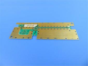
The stack-up of this Taconic TLX-8 PCB adopts a simplified and mechanically robust 2‑layer rigid structure, with uniform copper distribution and a thickTLX-8 core for stable high‑frequency transmission.
|
Layer |
Material & Thickness |
|
Copper Layer 1 |
35 μm |
|
TLX 8 Core |
30 mil (0.762 mm) |
|
Copper Layer 2 |
35 μm |
TLX-8 Material Introduction
At the heart of this PCB is TLX-8, a professional PTFE fiberglass laminate widely recognized for reliable performance across a wide range of RF and microwave applications. With a dielectric constant (Dk) ranging from 2.45 to 2.65, along with configurable thicknesses and copper cladding options, it delivers exceptional versatility for low‑layer‑count microwave designs. The fiberglass reinforcement provides robust mechanical support, allowing the substrate to withstand extreme environments that would degrade standard circuit materials.
TLX-8 performs reliably under severe mechanical and environmental stress: it resists creep in PCBs bolted to high‑vibration structures such as launch‑vehicle equipment; withstands high temperatures in engine modules; offers low outgassing and radiation resistance suitable for space applications (referenced in NASA low‑outgassing material lists); performs reliably in marine environments for naval antennas; and maintains dimensional stability over wide temperature swings in airborne altimeter systems. As a workhorse material in the RF and microwave industry,TLX-8 balances electrical performance, mechanical strength, and environmental durability in a single substrate.

Key Benefits of TLX-8
This TLX-8 Taconic PCB leverages the full advantages ofTLX-8 to deliver superior performance in high‑frequency systems:
These characteristics make the board highly suitable for applications where signal purity, stability, and reliability are non‑negotiable.
TLX-8 Data Sheet
|
TLX-8 TYPICAL VALUES |
|||||
|
Property |
Test Method |
Unit |
Value |
Unit |
Value |
|
DK @10 GHz |
IPC-650 2.5.5.3 |
|
2.55 |
|
2.55 |
|
Df @1.9 GHz |
IPC-650 2.5.5.5.1 |
|
0.0012 |
|
0.0012 |
|
Df @10 GHz |
IPC-650 2.5.5.5.1 |
|
0.0017 |
|
0.0017 |
|
Dielectric Breakdown |
IPC-650 2.5.6 |
kV |
>45 |
kV |
>45 |
|
Moisture Absorption |
IPC-650 2.6.2.1 |
% |
0.02 |
% |
0.02 |
|
Flexural Strength(MD) |
ASTM D 709 |
psi |
28,900 |
N/mm2 |
|
|
Flexural Strength(CD) |
ASTM D 709 |
psi |
20,600 |
N/mm2 |
|
|
Tensile Strength(MD) |
ASTM D 902 |
psi |
35,600 |
N/mm2 |
|
|
Tensile Strength(CD) |
ASTM D 902 |
psi |
27,500 |
N/mm2 |
|
|
Elongation at Break(MD) |
ASTM D 902 |
% |
3.94 |
% |
3.94 |
|
Elongation at Break(CD) |
ASTM D 902 |
% |
3.92 |
% |
3.92 |
|
Young's Modulus(MD) |
ASTM D 902 |
kpsi |
980 |
N/mm2 |
|
|
Young's Modulus(CD) |
ASTM D 902 |
kpsi |
1,200 |
N/mm2 |
|
|
Young's Modulus(MD) |
ASTM D 3039 |
kpsi |
1,630 |
N/mm2 |
|
|
Poisson's Ratio |
ASTM D 3039 |
|
0.135 |
N/mm |
|
|
Peel Stength(1 oz.ed) |
IPC-650 2.4.8 Sec.5.2.2(Thermal Stress.) |
Ibs./linear inch |
15 |
N/mm |
|
|
Peel Stength(1 oz.RTF) |
IPC-650 2.4.8 Sec.5.2.2(Thermal Stress.) |
Ibs./linear inch |
17 |
N/mm |
|
|
Peel Stength(½ oz.ed) |
IPC-650 2.4.8.3(Elevated Temp.) |
Ibs./linear inch |
14 |
N/mm |
|
|
Peel Stength(½ oz.ed) |
IPC-650 2.4.8 Sec.5.2.2(Thermal Stress.) |
Ibs./linear inch |
11 |
N/mm |
|
|
Peel Stength(1 oz.rolled) |
IPC-650 2.4.8 Sec.5.2.2(Thermal Stress.) |
Ibs./linear inch |
13 |
N/mm |
2.1 |
|
Thermal Conductivity |
ASTM F433/ASTM 1530-06 |
W/M*K |
0.19 |
W/M*K |
0.19 |
|
Dimensional Stability(MD) |
IPC-650 2.4.39 Sec.5.5(After Bake.) |
mils/in. |
0.06 |
mm/M |
|
|
Dimensional Stability(CD) |
IPC-650 2.4.39 Sec.5.4(After Bake.) |
mils/in. |
0.08 |
mm/M |
|
|
Dimensional Stability(MD) |
IPC-650 2.4.39 Sec.5.5(Thermal Stress.) |
mils/in. |
0.09 |
mm/M |
|
|
Dimensional Stability(CD) |
IPC-650 2.4.39 Sec.5.5(Thermal Stress.) |
mils/in. |
0.1 |
mm/M |
|
|
Surface Resistivity |
IPC-650 2.5.17.1 Sec.5.2.1(Elevated Temp.) |
Mohm |
6.605 x 10⁸ |
Mohm |
6.605 x 10⁸ |
|
Surface Resistivity |
IPC-650 2.5.17.1 Sec.5.2.1(Humidity Cond.) |
Mohm |
3.550 x 10⁶ |
Mohm |
3.550 x 10⁶ |
|
Volume Resistivity |
IPC-650 2.5.17.1 Sec.5.2.1(Elevated Temp.) |
Mohm/cm |
1.110 x 10¹⁰ |
Mohm/cm |
1.110 x 10¹⁰ |
|
Volume Resistivity |
IPC-650 2.5.17.1 Sec.5.2.1(Humidity Cond.) |
Mohm/cm |
1.046 x 10¹⁰ |
Mohm/cm |
1.046 x 10¹⁰ |
|
CTE(X axis)(25-260℃) |
IPC-650 2.4.41/ASTM D 3386 |
ppm/℃ |
21 |
ppm/℃ |
21 |
|
CTE(Y axis)(25-260℃) |
IPC-650 2.4.41/ASTM D 3386 |
ppm/℃ |
23 |
ppm/℃ |
23 |
|
CTE(Z axis)(25-260℃) |
IPC-650 2.4.41/ASTM D 3386 |
ppm/℃ |
215 |
ppm/℃ |
215 |
|
Density(Specific Gravity) |
ASTM D 792 |
g/cm3 |
2.25 |
g/cm3 |
2.25 |
|
Td(2% Weight Loss) |
IPC-650 2.4.24.6(TGA) |
℃ |
535 |
℃ |
|
|
Td(5% Weight Loss) |
IPC-650 2.4.24.6(TGA) |
℃ |
553 |
℃ |
|
|
Flammability Rating |
UL-94 |
|
V-0 |
|
V-0 |
Typical Applications
Thanks to its high-frequency performance and robust material properties, this 30mil TLX-8-based PCB supports a wide variety of RF and microwave components and systems:
Conclusion
This double-sided TLX-8 PCB represents a high‑reliability, high‑performance solution for modern RF and microwave applications. From material selection and structural design to manufacturing precision and final testing, every aspect is engineered to support stable, low‑loss signal transmission in demanding environments. The absence of solder mask and silkscreen supports specialized high‑frequency assembly needs, while immersion gold surface finishing ensures reliable soldering and long‑term contact stability. Backed by 100% electrical testing before shipment, this 30mil Taconic PCB provides consistent performance, durability, and quality for mission‑critical RF systems, making it an excellent choice for industrial, communication, aerospace, and marine applications requiring superior high‑frequency performance.


Previous:
6-Layer with Filled Via and 4-layer Isola FR408HR PCB with Blind Via ENIGNext:
Rogers TMM13i PCB 2-layer 15mil Microwave-grade Substrate ENIG No Solder MaskIf you have questions or suggestions,please leave us a message,we will reply you as soon as we can!
Categories
New Products

12-layer TG200 TU-872 SLK High-Speed FR4 1.68mm PCB with ENIG Impedance Control

12-Layer RO4350B + RO3010 3.14mm Hybrid PCB Nickel-Free EPIG Surface Finish Blind Via
8-Layer Hybrid PCB RO4003C + S1000-2M FR4 with ENIG Surface Finish Blind Via
6-Layer Isola Astra MT77 PCB with Blind Via & Resin Plug Immersion Silver Finish

2-Layer 20mil FSD1020T ENIG High-Frequency PCB with Via Resin Plugged and Capped

4-Layer F4BM265+S1000-2M Material Hyrbid PCB with Blind Via Impedance Control & ENIG

4-Layer Wangling WL-CT338 + FR4 Hybrid PCB ENIG Green Solder Mask White Silkscreen

6-layer Isola 370HR High-Tg FR-4 PCB 2μ" ENIG Impedance Controlled

RF-10 25mil Taconic PCB Materials stands out as a high-performance solution for RF applications. Its exceptional electrical properties, dimensional stability, thermal conductivity, and adhesion characteristics make it an ideal choice for demanding applications.
The PCB has a 4-layer hybrid stackup with a 0.5oz+plating ground layer, two 1oz ground layers, and a 0.5oz+plating signal layer.
The dimensions of the board are 55.00 x 26.00 mm, with a tolerance of +/- 0.15mm. The board has 16 components, 26 total pads, 9 through-hole pads, 10 top SMT pads, 7 bottom SMT pads, 77 vias, and 82 nets.
Rogers RO4003C PCB is an innovative and advanced circuit board that is made with high-quality materials.
The RO4350B PCB offers a range of benefits that make it an ideal choice for high-frequency applications. Its low dielectric loss and high thermal conductivity make it perfect for high-frequency applications such as RF and microwave circuits.
Bicheng PCB Ships High-Quality PCBs with Shengyi Tg150 ℃ S1000H Material and Advanced Stackup
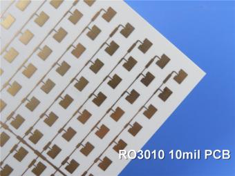
Rogers RO3010 PCB is ideal for a wide range of high-frequency applications, including power amplifiers, filters, couplers, and antennas.
TLX-8 features low dielectric loss, low moisture absorption, and excellent thermal stability, making it ideal for high-frequency and high-speed applications. It has a low dissipation factor, which helps to minimize signal loss and distortion.
 6-11C Shidai Jingyuan, Fuyong, Baoan, Shenzhen, Guangdong, China 518103


For inquiries about our products or pricelist, please leave to us and we will be in touch within 24 hours.
© Copyright: 2026 Shenzhen Bicheng Electronics Technology Co., Ltd.. All Rights Reserved.

IPv6 network supported


