

 Call Us Now !
Tel : +86 755 27374946
Call Us Now !
Tel : +86 755 27374946
 Order Online Now !
Email : info@bichengpcb.com
Order Online Now !
Email : info@bichengpcb.com
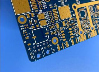
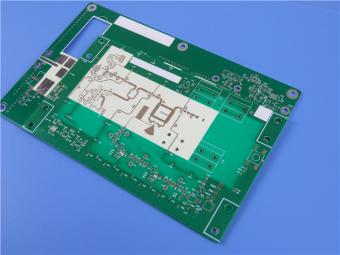
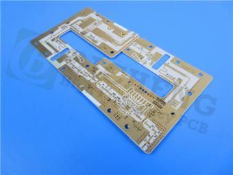
This 2-layer 10mil TLX-9 EPIG nickel-free PCB is a premium high-frequency solution built for ultra-low loss, exceptional stability, and long-term reliability.
Item NO.:
BIC-564-v649.0Order(MOQ):
1-10Payment:
T/TProduct Origin:
ChinaShipping Port:
ShenzhenLead Time:
7-10 days
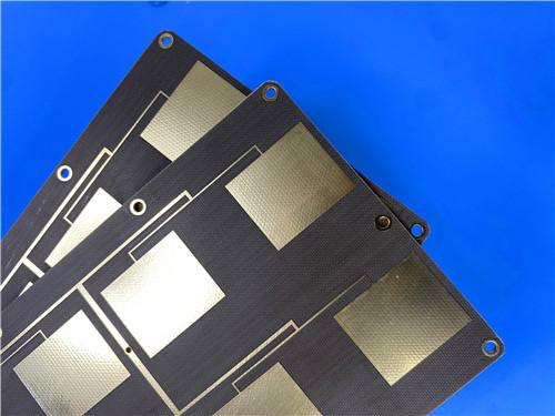
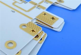
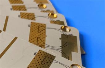
TLX-9 PCB 10mil 0.254mm Taconic High Frequency Laminate EPIG Nickle-free
1. Product Overview
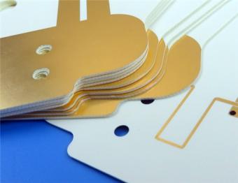
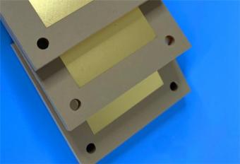
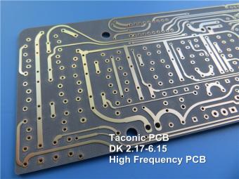
This is a high-performance 2-layer rigid high-frequency PCB built on Taconic TLX-9 PTFE/woven glass laminate with a 10mil (0.254mm) dielectric core and EPIG (Electroless Palladium Immersion Gold) nickel-free surface finishing. It is engineered for mission-critical RF, microwave, and millimeter-wave applications requiring ultra-stable dielectric properties, ultra-low signal loss, high dimensional stability, and long-term reliability in challenging environments.
Unlike standard FR-4 or high-frequency boards with ENIG (which contains a nickel interlayer), this Taconic PCB uses EPIG nickel-free finishing to avoid magnetic loss, signal degradation, and reliability risks from nickel corrosion or diffusion—especially critical for high-sensitivity receivers, high-power amplifiers, and precision passive components. The 10mil thin-core structure supports miniaturization, impedance control, and improved high-frequency response, while Taconic TLX-9’s tightly controlled Dk 2.50 and Df 0.0019 @10GHz ensure consistent performance across wide frequency and temperature ranges.
2. PCB Construction Details
This section summarizes the 10mil TLX-9 board’s mechanical, structural, and surface processing parameters, defining its manufacturability, miniaturization capability, and reliability.
|
Item |
Specification |
|
Base Material |
Taconic TLX-9 (PTFE/woven glass laminate) |
|
Layer Count |
2 layers |
|
Board Dimensions |
91.6mm × 45.3mm per piece, tolerance ±0.15mm |
|
Minimum Trace / Space |
5 / 6 mils |
|
Minimum Hole Size |
0.3mm |
|
Blind Vias |
None |
|
Finished Board Thickness |
0.3mm |
|
Finished Copper Weight |
1oz (1.4 mils) on outer layers |
|
Via Plating Thickness |
20 μm |
|
Surface Finish |
EPIG (Nickel-Free) |
|
Top Silkscreen |
No |
|
Bottom Silkscreen |
No |
|
Top Solder Mask |
No |
|
Bottom Solder Mask |
No |
|
Pre-Shipment Test |
100% Electrical Test |
3. PCB Stackup
The stackup defines the layer structure, dielectric thickness, and copper distribution, directly determining impedance, thermal behavior, and high-frequency performance.
|
Layer |
Material |
Thickness |
|
Copper Layer 1 (Top) |
Electrodeposited Copper |
35 μm (1oz) |
|
Core Dielectric |
Taconic TLX-9 |
0.254mm (10mil) |
|
Copper Layer 2 (Bottom) |
Electrodeposited Copper |
35 μm (1oz) |
Structure note: Symmetrical 2-layer rigid construction with balanced copper distribution, supporting stable impedance control and minimal warpage.
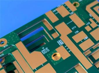
4. PCB Layout & Net Statistics
These statistics reflect component density, pad distribution, and routing complexity for assembly and application matching.
|
Item |
Quantity |
|
Total Components |
29 |
|
Total Pads |
45 |
|
Through-Hole Pads |
24 |
|
Top SMT Pads |
21 |
|
Bottom SMT Pads |
0 |
|
Vias |
19 |
|
Nets |
2 |

5. Core Technical Advantages & Differentiators
5.1 Ultra-Stable Dielectric Performance
TLX-9 provides Dk = 2.50±0.04 @10GHz with exceptional consistency across frequency and temperature. Its Df = 0.0019 @10GHz delivers extremely low insertion loss, making it ideal for LNAs, LNBs, high-power amplifiers, and precision passive components where signal purity is critical.
5.2 Nickel-Free EPIG Surface Finish
Compared with conventional ENIG:
This is strongly preferred for high-sensitivity RF frontends and space/avionics hardware.
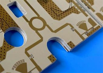
5.3 10mil Thin-Core High-Density Design
5.4 Excellent Mechanical & Environmental Stability
6. Typical Applications
This TLX-9 Taconic High Frequency PCB is optimized for:
7. TLX-9 CCL (Copper Clad Laminate) Technical Knowledge
This section is independent from the PCB description and provides in-depth CCL fundamentals, specifications, and comparative value for material selection and design review.
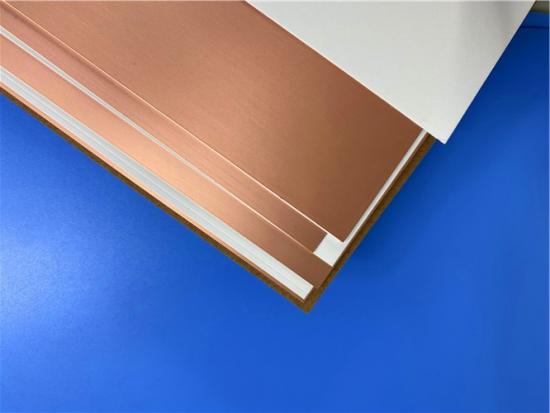
7.1 What is PTFE/Woven Glass CCL?
Copper Clad Laminate (CCL) is the core substrate of PCBs.PTFE/woven glass CCL combines polytetrafluoroethylene (PTFE) polymer with woven glass reinforcement, bonded to electrolytic copper foil. It is the dominant material for high-frequency, low-loss, high-stability RF/microwave PCBs due to:

7.2 TLX-9 CCL Full Datasheet Table (Tested per IPC-TM-650 & ASTM)
|
Property |
Test Standard |
Unit |
Typical Value |
|
Dielectric Constant (10GHz) |
IPC-TM-650 2.5.5.5 |
— |
2.50 ±0.04 |
|
Dissipation Factor (10GHz) |
IPC-TM-650 2.5.5.5 |
— |
0.0019 |
|
Moisture Absorption |
IPC-TM-650 2.6.2.1 |
% |
<0.02 |
|
Dielectric Breakdown |
IPC-TM-650 2.5.6 |
kV |
>60 |
|
Volume Resistivity |
IPC-TM-650 2.5.17.1 |
MΩ·cm |
10⁷ |
|
Surface Resistivity |
IPC-TM-650 2.5.17.1 |
MΩ |
10⁷ |
|
Arc Resistance |
IPC-TM-650 2.5.1 |
sec |
>180 |
|
Flexural Strength (Lengthwise) |
IPC-TM-650 2.4.4 |
N/mm² |
>159 |
|
Flexural Strength (Crosswise) |
IPC-TM-650 2.4.4 |
N/mm² |
>131 |
|
Peel Strength (1oz Cu) |
IPC-TM-650 2.4.8 |
N/mm |
2.1 |
|
Thermal Conductivity |
ASTM F433 |
W/m/K |
0.19 |
|
x-y CTE |
ASTM D3386 (TMA) |
ppm/°C |
9–12 |
|
z-CTE |
ASTM D3386 (TMA) |
ppm/°C |
130–145 |
|
Flammability |
UL 94 |
— |
V-0 |
7.3 TLX Series CCL Dielectric Constant Comparison
|
Grade |
Dk @10GHz |
Tolerance |
|
TLX-0 |
2.45 |
±0.04 |
|
TLX-9 |
2.5 |
±0.04 |
|
TLX-8 |
2.55 |
±0.04 |
|
TLX-7 |
2.6 |
±0.04 |
|
TLX-6 |
2.65 |
±0.0 |
7.4 Key Advantages of TLX-9 CCL
7.5 Why TLX-9 Outperforms General High-Frequency Materials
8. Conclusion
This 2-layer 10mil TLX-9 EPIG nickel-free PCB is a premium high-frequency solution built for ultra-low loss, exceptional stability, and long-term reliability. Backed by TLX-9’s industry-proven dielectric performance and EPIG’s nickel-free high-frequency advantage, it satisfies the most demanding RF/microwave applications while complying with IPC-Class 2 and full quality assurance.
The thin 10mil core, fine-line capability, and zero solder mask / silkscreen configuration make it especially suitable for miniaturized, high-sensitivity, high-power RF modules. The accompanying detailed TLX-9 laminate datasheet provides full transparency for material selection, simulation, reliability assessment, and supply chain management.


If you have questions or suggestions,please leave us a message,we will reply you as soon as we can!
Categories
New Products
RO4835 20mil Rogers Laminate 2-layer Immersion Gold Custom PCB
Rogers 20mil DiClad 527 PCB 2-layer Immersion Gold No Solder Mask Black Silkscreen
Wangling WL-CT300 5mil Laminate Pure Gold Plating High Frequency PCB
Wangling TF300 25mil DK3.0 Laminate 2-layer PCB Immersion Gold Black Silkscreen
2-Layer 0.5mm TP440 PCB Wangling TP DK4.4 Laminate Immersion Gold
20-Layer Panasonic TU872 HDI PCB ENEPIG 3.0mm Finished Thick Laser-drilled Blind Vias
10-Layer Rogers RO4003C + 370HR FR4 Hybrid Laminate PCB ENIG Impedance Control
8-Layer 10oz Heavy Copper TU-865 Substrate PCB With ENIG Blind &Buried Via
RF-35TC is a type of high frequency material from Taconic company. It offers a "best in class" low dissipation factor with high thermal conductivity.
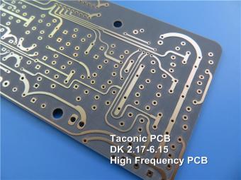
TLX offers reliability in a wide range of RF applications. This material is versatile due to its 2.45 - 2.65 DK range and available thicknesses and copper cladding. It is suitable for low layer count microwave designs.

TLF-35A is another type of low cost RF material. It's the best choice for low cost, high volume commercial microwave and radio frequency applications.
CER-10 is an organic-ceramic DK-10 laminate in the ORCER family of Taconic products. It is based on a woven glass reinforcement. CER-10 exhibits exceptional interlaminar bond strength and solder resistance.
RO4360G2 laminates of Rogers Corporation are 6.15 Dk, low loss, glass-reinforced, hydrocarbon ceramic-filled thermoset materials that provide the ideal balance of performance and processing ease.
RF-60A is an organic-ceramic laminate in the ORganic CERamic(ORCER) family of Taconic products.
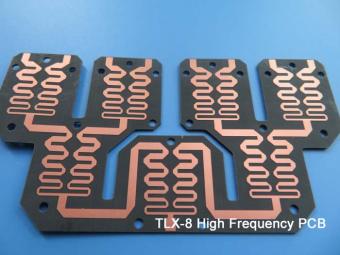
TLX is PTFE based fiberglass laminate, it is ideal for use in radar systems, mobile communications, microwave test equipment, microwave transmission devices and RF components.
TLX offers reliability in a wide range of RF applications. This material is versatile due to its 2.45 - 2.65 DK range and available thicknesses and copper cladding. It is suitable for low layer count microwave designs
 6-11C Shidai Jingyuan, Fuyong, Baoan, Shenzhen, Guangdong, China 518103


For inquiries about our products or pricelist, please leave to us and we will be in touch within 24 hours.
© Copyright: 2026 Shenzhen Bicheng Electronics Technology Co., Ltd.. All Rights Reserved.

IPv6 network supported


