

 Call Us Now !
Tel : +86 755 27374946
Call Us Now !
Tel : +86 755 27374946
 Order Online Now !
Email : info@bichengpcb.com
Order Online Now !
Email : info@bichengpcb.com
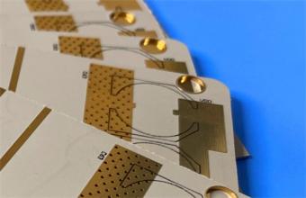
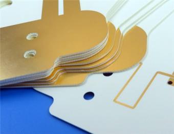
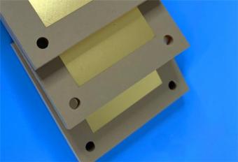
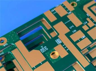
This RO4533 20mil 2-layer immersion gold PCB delivers exceptional high-frequency performance, mechanical reliability, and production efficiency for antenna and RF applications.
Item NO.:
BIC-562-v647.0Order(MOQ):
1-10Payment:
T/TProduct Origin:
ChinaShipping Port:
ShenzhenLead Time:
7-10 days
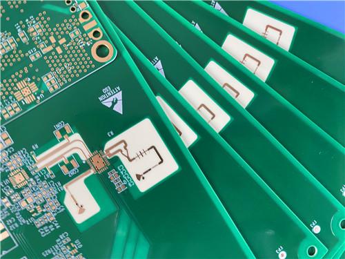
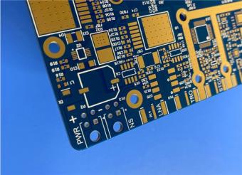
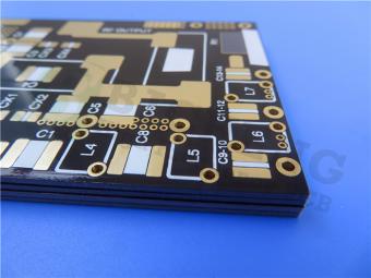
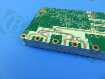
2-layer RO4533 PCB 20mil Rogers Laminate Immersion Gold Green Solder Mask
1. Product Overview
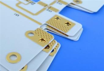
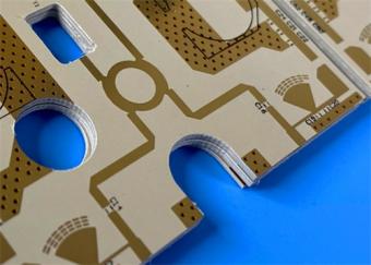
This is a high-performance 2-layer rigid printed circuit board engineered around Rogers RO4533 hydrocarbon ceramic-filled laminate, optimized for microstrip antennas, passive intermodulation (PIM)-sensitive circuits, and high-frequency signal transmission up to 10 GHz and beyond. The Rogers board adopts a 20mil (0.508mm) core thickness, 1oz outer copper, immersion gold surface finish, and IPC-Class-2 quality assurance, delivering a balanced combination of electrical performance, mechanical stability, process compatibility, and cost efficiency.
Unlike PTFE-based high-frequency substrates, Rogers 4533 supports standard FR-4-compatible fabrication and lead-free assembly without special surface treatment for plated through-holes, greatly improving production yield and reducing total cost of ownership (TCO) for volume deployment.
Designed for mobile infrastructure, base station antennas, WiMAX networks, and other RF front-end modules, this 20mil Rogers PCB ensures low insertion loss, stable dielectric constant, minimal PIM, and robust thermomechanical reliability under thermal cycling and humid operating environments. Every unit undergoes 100% electrical testing before shipment to guarantee functional consistency and long-term durability.
2. PCB Construction Details
This section summarizes the complete mechanical, surface, and fabrication specifications of the finished PCB in a structured table.
|
Item |
Specification |
|
Base Material |
Rogers RO4533 |
|
Layer Count |
2 layers |
|
Board Dimension |
123.5mm × 46mm (per piece), tolerance ±0.15mm |
|
Minimum Trace / Space |
4/5 mils |
|
Minimum Finished Hole Size |
0.25mm |
|
Blind Vias |
Not applicable |
|
Finished Board Thickness |
0.6mm |
|
Finished Copper Weight (Outer Layers) |
1oz (≈1.4 mils / 35μm) |
|
Via Plating Thickness |
20μm |
|
Surface Finish |
Immersion Gold (ENIG) |
|
Top Silkscreen |
White |
|
Bottom Silkscreen |
None |
|
Top Solder Mask |
Green |
|
Bottom Solder Mask |
None |
|
Quality Standard |
IPC-Class-2 |
|
Pre Shipment Test |
100% electrical continuity & isolation test |
3. PCB Stack-Up Structure
The stack-up defines the layer sequence, dielectric thickness, and copper distribution, directly influencing impedance control, signal loss, and thermal behavior.
|
Layer |
Material |
Thickness |
|
Outer Copper Layer 1 |
Electrodeposited Copper |
35μm (1oz) |
|
Core Dielectric |
Rogers RO4533 |
0.508mm (20mil) |
|
Outer Copper Layer 2 |
Electrodeposited Copper |
35μm (1oz) |
4. PCB Layout & Net Statistics
This table summarizes component, pad, via, and net density for assembly and design verification.
|
Parameter |
Quantity |
|
Total Components |
36 |
|
Total Pads |
28 |
|
Through-Hole Pads |
18 |
|
Top SMT Pads |
10 |
|
Bottom SMT Pads |
0 |
|
Vias |
17 |
|
Electrical Nets |
2 |

5. Core Product Advantages & Differentiators
5.1 Electrical Performance for High-Frequency Systems
5.2 Thermomechanical Reliability
5.3 Manufacturing & Cost Advantages
5.4 Surface & Structural Quality
6. Target Applications
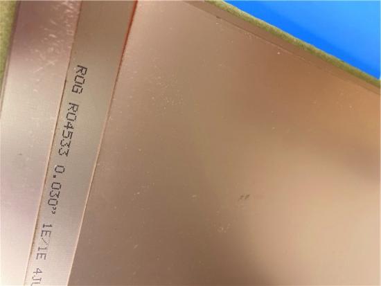
Part 2–RO4533 Copper Clad Laminate (CCL) Technical Knowledge & Full Datasheet
This section is completely independent from the RO4533 high frequency PCB description, focusing on material science, classification, key properties, test methods, and full datasheet parameters ofRogers RO4533laminate.
1. What is High-Frequency Copper Clad Laminate (CCL)?
Copper Clad Laminate (CCL) is the foundational substrate of PCBs, composed of reinforced material (glass fabric), resin system, and copper foil bonded under heat and pressure. For high-frequency (≥1 GHz) and microwave applications, CCL must deliver:
RO4533 belongs to Rogers RO4500 Series, a cost-optimized antenna-grade hydrocarbon ceramic laminate family designed to replace high-cost PTFE substrates while retaining performance for antenna and RF applications.

2. Material Classification & Positioning
3. Full RO4533 CCL Datasheet Parameters (Tested per IPC & ASTM Standards)
|
Property |
Typical Value |
Direction |
Unit |
Condition |
Test Standard |
|
Dielectric Constant (Dk) |
3.3 ±0.08 |
Z |
– |
10 GHz, 23°C |
IPC-TM-650 2.5.5.5 |
|
Dissipation Factor (Df) |
0.0025 |
Z |
– |
10 GHz, 23°C |
IPC-TM-650 2.5.5.5 |
|
Dissipation Factor (Df) |
0.002 |
Z |
– |
2.5 GHz, 23°C |
IPC-TM-650 2.5.5.5 |
|
Passive Intermodulation (PIM) |
–157 |
– |
dBc |
43 dBm swept tones, 1900 MHz |
Summitek 1900b |
|
Dielectric Strength |
>500 |
Z |
V/mil |
0.51mm |
IPC-TM-650 2.5.6.2 |
|
Dimensional Stability |
<0.2 |
X,Y |
mm/m |
After etching |
IPC-TM-650 2.4.39A |
|
CTE (X) |
13 |
X |
ppm/°C |
–55 to 288°C |
IPC-TM-650 2.4.41 |
|
CTE (Y) |
11 |
Y |
ppm/°C |
–55 to 288°C |
IPC-TM-650 2.4.41 |
|
CTE (Z) |
37 |
Z |
ppm/°C |
–55 to 288°C |
IPC-TM-650 2.4.41 |
|
Thermal Conductivity |
0.6 |
– |
W/m·K |
80°C |
ASTM C518 |
|
Moisture Absorption |
0.02 |
– |
% |
D48/50 |
IPC-TM-650 2.6.2.1 / ASTM D570 |
|
Glass Transition Temperature (Tg) |
>280 |
– |
°C |
TMA |
IPC-TM-650 2.4.24.3 |
|
Density |
1.8 |
– |
g/cm³ |
– |
ASTM D792 |
|
Copper Peel Strength |
6.9 lbs/in (1.2 N/mm) |
– |
lbs/in / N/mm |
1oz EDC, post solder float |
IPC-TM-650 2.4.8 |
|
Flammability |
NON FR |
– |
– |
– |
UL 94 |
|
Lead-Free Compatibility |
Yes |
– |
– |
– |
– |
4. Standard Specifications of RO4533 CCL
|
Description |
Specification |
|
Standard Core Thickness |
0.508mm (20mil), 0.762mm (30mil), 1.524mm (60mil) |
|
Standard Panel Sizes |
610×457mm; 610×533mm; 610×915mm; 1219×915mm |
|
Standard Copper Cladding |
½ oz (18μm), 1oz (35μm) ED copper |
5. Key CCL Performance Advantages Explained
1)Low Loss & Stable Dk
Enables high antenna gain, low noise, and consistent performance across frequency bands.
2)Low PIM Characteristic
Reduces intermodulation interference in multi-operator, multi-carrier cellular systems.
3)CTE Matching with Copper
Minimizes thermomechanical stress, extending service life under thermal cycling.
4)High Tg & Low Z-CTE
Strengthens via reliability and prevents warpage during assembly.
5)Low Moisture Absorption
Preserves electrical stability in harsh outdoor environments.
6)Standard Fabrication Compatibility
Eliminates PTFE-type special processes, cutting cost and lead time.
7)Halogen-Free Green Option
Complies with global environmental regulations.
6. Typical CCL-Level Applications
7.Conclusion
This RO4533 20mil 2-layer immersion gold PCB delivers exceptional high-frequency performance, mechanical reliability, and production efficiency for antenna and RF applications. It features stable Dk 3.3, ultra-low loss, excellent PIM, and copper-matched CTE for long-term durability.
Rogers RO4533 substrate bridges the gap between FR-4 and expensive PTFE materials, supporting standard PCB and lead-free processes while lowering costs and improving yields. With immersion gold, controlled plating, and halogen-free compliance, this 20mil RO4533 PCB offers an optimal balance of electrical performance, assembly compatibility, and environmental responsibility. It is a reliable, cost-effective, and production-ready solution for cellular base stations, WiMAX networks, and high-reliability wireless infrastructure.


Previous:
2-Layer RT/duroid 6006 PCB 10mil Rogers Substrate Immersion Silver No Solder MaskNext:
2-Layer RO4350B LoPro PCB 4mil Rogers Substrate Immersion Gold Blue Solder MaskIf you have questions or suggestions,please leave us a message,we will reply you as soon as we can!
Categories
New Products
RO4835 20mil Rogers Laminate 2-layer Immersion Gold Custom PCB
Rogers 20mil DiClad 527 PCB 2-layer Immersion Gold No Solder Mask Black Silkscreen
Wangling WL-CT300 5mil Laminate Pure Gold Plating High Frequency PCB
Wangling TF300 25mil DK3.0 Laminate 2-layer PCB Immersion Gold Black Silkscreen
2-Layer 0.5mm TP440 PCB Wangling TP DK4.4 Laminate Immersion Gold
20-Layer Panasonic TU872 HDI PCB ENEPIG 3.0mm Finished Thick Laser-drilled Blind Vias
10-Layer Rogers RO4003C + 370HR FR4 Hybrid Laminate PCB ENIG Impedance Control
8-Layer 10oz Heavy Copper TU-865 Substrate PCB With ENIG Blind &Buried Via
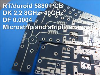
This is a type of double sided RF PCB built on RT/duroid 5880 for the application of Radar Systems.
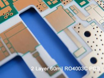
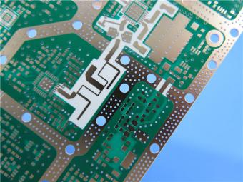
RO4003C PCBs are hydrocarbon ceramic filled laminates, not PTFE which are designed to offer superior high frequency performance.
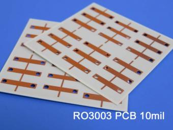
Rogers RO3003 high frequency circuit materials are ceramic-filled PTFE composites intended for use in commercial microwave and RF applications. It was designed to offer exceptional electrical and mechanical stability at competitive prices.
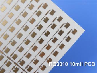
RO3010 laminates are competitively priced products with exceptional mechanical and electrical stability. This stability simplifies the design of broadband components and allows the materials to be used in a wide range of applications over a very broad range of frequencies.
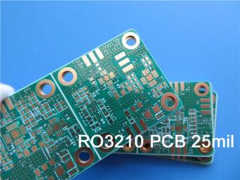
These RO3210 materials are engineered to offer exceptional electrical performance and mechanical stability. RO3210 laminates combine the surface smoothness of a non-woven PTFE laminate.
RT/duroid 6035HTC laminates are an exceptional choice for high power applications.
TC350 is designed to provide enhanced heat-transfer through “Best-In-Class” thermal conductivity, while reducing dielectric loss and insertion loss. Lower losses result in higher Amplifier and Antenna Gains/Efficiencies.
RO3035 materials exhibit a coefficient of thermal expansion(CTE) in the X and Y axis of 17 ppm/℃. This expansion coefficient is matched to that of copper, which allows the material to exhibit excellent dimensional stability.
 6-11C Shidai Jingyuan, Fuyong, Baoan, Shenzhen, Guangdong, China 518103


For inquiries about our products or pricelist, please leave to us and we will be in touch within 24 hours.
© Copyright: 2026 Shenzhen Bicheng Electronics Technology Co., Ltd.. All Rights Reserved.

IPv6 network supported


