
 Call Us Now !
Tel : +86 755 27374946
 Order Online Now !
Email : info@bichengpcb.com
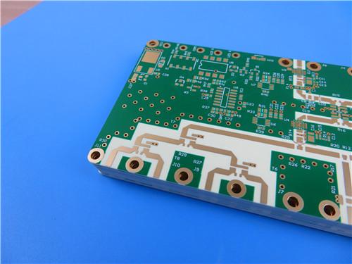
This 10-layer RO4350B + TU-768 hybrid PCB answers a specific engineering question honestly: how to put controlled 50 Ω RF on both outer faces of a thick, 10-layer module without paying for ten layers of ceramic laminate.
Item NO.:
BIC-639-v723Order(MOQ):
1-10Payment:
T/TProduct Origin:
ChinaShipping Port:
ShenzhenLead Time:
7-10 days
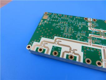
10-Layer RO4350B + TU-768 Hybrid PCB with Via Copper Capped ENIG Surface Finish
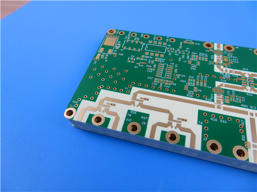
When RF performance, layer count and bill-of-material cost all matter at once, ahybrid dielectric stack is the most disciplined engineering answer. This 10-layer board places Rogers RO4350B high-frequency laminate only on the two outer-facing cores — a 10 mil layer on top and a 10 mil layer on the bottom — while the inner cores and every prepreg sheet are built from TU-768, a Tg170 °C high-reliability FR-4. The panel is finished at 2.5 mm with 1 oz copper on all ten layers, 25 μm plated hole walls, resin-plugged and copper-capped vias, immersion gold, green solder mask with white silkscreen and IPC-6012D Class 3 acceptance. It is designed for RF front-end modules that must combine controlled-impedance microwave lines with dense inner routing and real lead-free assembly.
1. Product architecture at a glance
The construction follows one principle: spend the premium dielectric on the layers that carry RF energy, and use a proven high-Tg FR-4 where the signals are predominantly control, power and digital. Each RO4350B core forms an outer copper pair, L1–L2 and L9–L10; the three inner pairs, L3–L4, L5–L6 and L7–L8, use TU-768 cores, and TU-768P prepreg bonds all five cores together.
Because the stack is electrically and mechanically symmetric — mirrored 2116 prepreg pairs near the outside and 1080 pairs at the centre — both faces see nearly identical dielectric conditions. That keeps outer-layer impedance balanced and suppresses bow and twist in a board as thick as 2.5 mm.
Typical applications include cellular base-station antennas and power amplifiers, automotive radar and sensors, low-noise blocks (LNBs) for direct-broadcast satellite, and RF identification hardware.
2. PCB Construction details
Table 1 consolidates the controlled manufacturing parameters of the build, from the hybrid laminate system and copper weight to via treatment, surface finish and acceptance class.
Table 1. PCB Construction details
|
Item |
Specification |
|
Base material |
Hybrid stackup: 10 mil RO4350B hydrocarbon ceramic cores on TOP and BOTTOM; TU-768 (Tg170 °C) high-Tg FR-4 cores and TU-768P prepreg in the middle |
|
Layer count |
10 layers |
|
Board dimensions |
132 mm × 76.5 mm = 1 PCS (tooling / process rails included) |
|
Finished board thickness |
2.5 mm |
|
Finished copper weight |
1 oz (35 μm) on all layers |
|
Via plating thickness |
25 μm copper in the hole |
|
Via treatment |
Resin plugged and copper plated flat (copper capped / POFV) |
|
Surface finish |
Immersion gold (ENIG), 140%–150% |
|
Top solder mask |
Green |
|
Bottom solder mask |
Green |
|
Top silkscreen |
White |
|
Bottom silkscreen |
White |
|
Acceptance standard |
IPC-6012D Class 3 |
|
Electrical test |
100% electrical test prior to shipment |
3. Two 10 mil RO4350B faces: where the RF performance comes from
Rogers RO4350B is a glass-reinforced hydrocarbon/ceramic laminate — not a PTFE material. Its process dielectric constant is 3.48 ± 0.05 at 10 GHz and its dissipation factor is 0.0037 at 10 GHz, roughly one sixth of the TU-768 inner dielectric at the same frequency (0.023). Routing RF lines on a dielectric this low-loss means lower insertion loss, less energy converted to heat in the substrate and flatter return loss across the band.
The 10 mil (0.254 mm) dielectric thickness also gives impedance engineers useful geometry headroom. A 50 Ω microstrip line and a wide range of controlled-impedance pairs can be produced with practical, manufacturable trace widths rather than fragile, over-etch-sensitive narrow lines.
The second benefit is stability. RO4350B keeps a dielectric-constant temperature coefficient of +50 ppm/°C from −50 °C to 150 °C, its design Dk stays close to flat from 8 to 40 GHz, and its Tg is above 280 °C. Its X/Y CTE of 10 and 12 ppm/°C is close to copper, protecting plated-through holes through thermal cycling. The same RO4350B core on both faces makes the two RF layers electrically interchangeable, simplifies impedance modelling and removes the asymmetry that would pull a thick panel into bow and twist. RO4350B is UL 94 V-0 rated and processes on standard FR-4 lines, so no specialised PTFE via-preparation step such as sodium etching is required.
4. TU-768 Tg170 inner layers: cost, thermal and mechanical balance
Eight of the ten copper layers sit on TU-768, a Taiwan Union Technology (TUC) high-Tg FR-4 with a Tg of 170 °C by TMA (190 °C by DMA) and a decomposition temperature of 350 °C. Substituting high-Tg FR-4 on the inner pairs removes the largest cost penalty of an all-ceramic multilayer without touching the layers that actually carry microwave energy — the core economic argument for hybrid volume production.
The inner material also does structural work. TU-768 is qualified for lead-free assembly, surviving a 288 °C solder float for more than 60 seconds and the T288 thermal test for more than 15 minutes, giving margin for double-sided or repeated reflow cycles. Its X/Y CTE of 11–15 ppm/°C is close to that of RO4350B, an important coincidence that limits interlayer stress in a mixed-dielectric press. Anti-CAF performance, 0.18% water absorption and strong chemical resistance address long-term insulation reliability. With a Dk of about 4.3 at 10 GHz, the inner cores suit the control, power-supply and low-speed digital layers of an RF module, while their rigid E-glass reinforcement gives the 2.5 mm panel most of its bending stiffness and flatness.
5. Building a 2.5 mm, 10-layer hybrid: where the process risk is controlled
A 10-layer, 2.5 mm hybrid PCB is not a routine press job. The two dielectrics differ in resin chemistry, resin flow and Z-axis expansion — 32 ppm/°C for RO4350B versus 2.7% total Z expansion for TU-768 — so lamination uses gradient heating, staged dwell times and controlled cooling rather than a single ramp. Registration targets and uniform-pressure caul plates prevent layer shift and uneven dielectric squeeze-out across the 132 mm × 76.5 mm panel. Thickness is accumulated from five 0.254 mm cores, four prepreg pairs and ten 0.035 mm copper layers, giving a 2.37 mm pressed stack that reaches 2.5 mm after outer-layer processing and solder mask.
Reliability is then built in at the holes and pads. Every plated-through hole carries 25 μm of copper in the wall — the IPC-6012D Class 3 level rather than the consumer Class 2 minimum. Through vias are resin plugged and electroplated flat (POFV, copper-capped), so SMD pads can sit directly over sealed vias without paste voids, outgassing or solder wicking into the barrel. Immersion gold (ENIG, 140%–150%) provides a flat, coplanar, oxidation-free contact surface; green solder mask and white silkscreen finish both faces; and every panel passes 100% electrical test before shipment.
6. PCB Stackup
Table 2 and Figure 1 document the symmetric layer-by-layer build, with the two RO4350B cores at the outside and mirrored 2116/1080 prepreg pairs converging on the centre.
Table 2. PCB Stackup (10 layers, 2.5 mm finished)
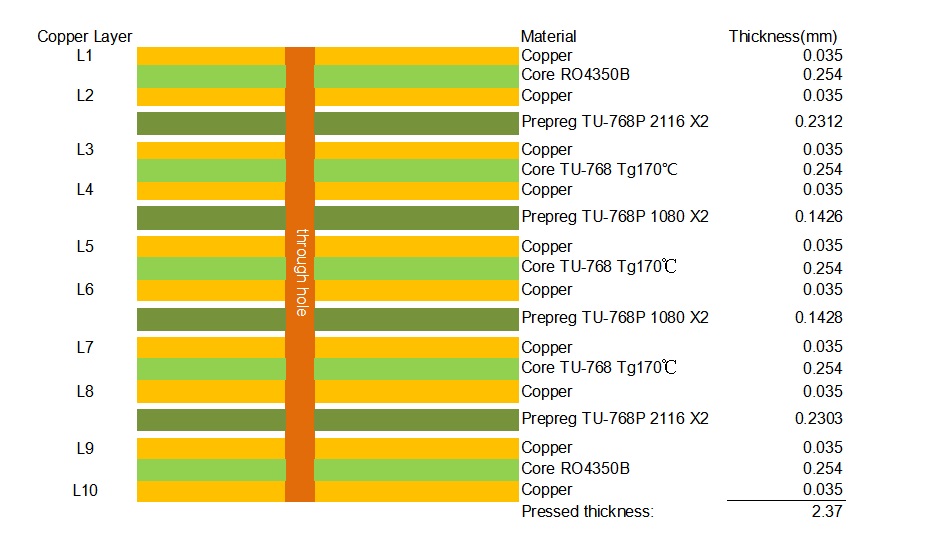
Figure 1. Engineering stackup drawing of the 10-layer RO4350B + TU-768 hybrid board (pressed thickness 2.37 mm).
7. Typical applications
It suits high-layer-count RF modules that mix a microwave front-end with digital control and power distribution:
8. Conclusion
This 10-layer RO4350B + TU-768 hybrid PCB answers a specific engineering question honestly: how to put controlled 50 Ω RF on both outer faces of a thick, 10-layer module without paying for ten layers of ceramic laminate. The RO4350B skins deliver the Dk, Df and thermal stability the RF lines need; the TU-768 inner stack delivers Tg170 lead-free assembly margin, CAF resistance and mechanical rigidity at FR-4 cost; and a Class 3 process envelope — 25 μm hole copper, resin-plugged copper-capped vias, ENIG and 100% electrical test — closes the reliability gap. For volume RF modules combining analog front-ends with dense inner routing, it is a balanced, manufacturable and tightly specified construction rather than an over-designed one.
Appendix: CCL Knowledge — RO4350B and TU-768
A copper-clad laminate (CCL) is the raw board material: a dielectric resin system with its reinforcement, bonded to copper foil on one or both faces. A core is a rigid CCL with copper on both sides; prepreg is the B-stage, partially cured bonding glass that joins cores during lamination. In a hybrid board, each CCL is selected for the job its layers actually perform, rather than applying one premium material throughout. The following two sections document the two laminates used in this product, using the manufacturers’ published data.
A. Rogers RO4350B high-frequency hydrocarbon ceramic laminate
RO4350B belongs to the Rogers RO4000 series of reinforced hydrocarbon/ceramic laminates. It is not PTFE-based: it is a rigid, thermoset material that fabricates on standard epoxy/glass (FR-4) processes and automated handling equipment, and it does not require the sodium-etch via preparation that PTFE boards demand. RO4350B uses RoHS-compliant flame-retardant technology for applications requiring UL 94 V-0 certification; it conforms to IPC-4103 slash sheets /11 and /240 (the 4 mil thickness is qualified separately to /240).
The material’s value to an RF designer is the combination of low loss, tight dielectric tolerance and stable properties. Its process Dk is 3.48 ± 0.05 at 10 GHz, with a design Dk of 3.66 across 8–40 GHz, and its Df is 0.0037 at 10 GHz. Its dielectric-constant temperature coefficient, +50 ppm/°C, is among the lowest of any circuit material, and its Z-axis CTE of 32 ppm/°C together with a Tg above 280 °C gives reliable plated-through-hole quality under thermal shock. The charts below, taken from the Rogers data sheet, show how flat Dk remains with temperature and frequency, and how microstrip insertion loss compares with LoPro reverse-treated-foil options.
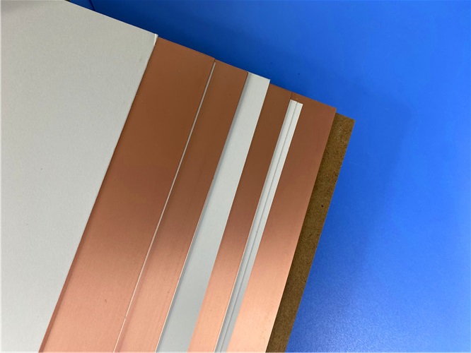
Figure A.1. RO4000 series hydrocarbon ceramic CCL sheets (Rogers).
Table A.1. RO4350B typical properties (source: Rogers RO4000 series data sheet, Pub# 92-004)
|
Property |
RO4350B value |
Unit |
Condition |
Test method |
|
Thermal / electrical |
|
|
|
|
|
Dielectric constant, εr — process |
3.48 ± 0.05 |
— |
10 GHz / 23 °C |
IPC-TM-650 2.5.5.5, clamped stripline |
|
Dielectric constant, εr — design |
3.66 |
— |
8–40 GHz |
Differential phase length method |
|
Dissipation factor, tan δ |
0.0037 / 0.0031 |
— |
10 GHz / 2.5 GHz, 23 °C |
IPC-TM-650 2.5.5.5 |
|
Thermal coefficient of εr |
+50 |
ppm/°C |
−50 °C to 150 °C |
IPC-TM-650 2.5.5.5 |
|
Volume resistivity |
1.2 × 10¹⁰ |
MΩ·cm |
Cond A |
IPC-TM-650 2.5.17.1 |
|
Surface resistivity |
5.7 × 10⁹ |
MΩ |
Cond A |
IPC-TM-650 2.5.17.1 |
|
Electrical strength |
31.2 (780) |
kV/mm (V/mil) |
0.51 mm (0.020") |
IPC-TM-650 2.5.6.2 |
|
Mechanical |
|
|
|
|
|
Tensile modulus (X / Y) |
16,767 / 14,153 |
MPa |
Room temperature |
ASTM D638 |
|
Tensile strength (X / Y) |
203 / 130 |
MPa |
Room temperature |
ASTM D638 |
|
Flexural strength |
255 (37) |
MPa (kpsi) |
— |
IPC-TM-650 2.4.4 |
|
Dimensional stability |
< 0.5 |
mm/m |
After etch + E2/150 °C |
IPC-TM-650 2.4.39A |
|
Thermal / physical |
|
|
|
|
|
CTE (X / Y / Z) |
10 / 12 / 32 |
ppm/°C |
−55 °C to 288 °C |
IPC-TM-650 2.4.41 |
|
Tg |
> 280 |
°C (TMA) |
— |
IPC-TM-650 2.4.24.3 |
|
Td |
390 |
°C (TGA) |
— |
ASTM D3850 |
|
Thermal conductivity |
0.69 |
W/(m·K) |
80 °C |
ASTM C518 |
|
Moisture absorption |
0.06 |
% |
48 h immersion, 50 °C |
ASTM D570 |
|
Density |
1.86 |
g/cm³ |
23 °C |
ASTM D792 |
|
Copper peel strength |
0.88 (5.0) |
N/mm (pli) |
After solder float, 1 oz EDC foil |
IPC-TM-650 2.4.8 |
|
Flammability |
V-0 |
— |
— |
UL 94 |
|
Lead-free process compatible |
Yes |
— |
— |
— |
Standard availability (RO4350B): thicknesses from 0.004" (0.10 mm) to 0.060" (1.52 mm), including the 0.010" (0.25 mm) ±0.0010" grade used on this board; standard panel sizes 24"×18", 24"×21", 24"×36" and 48"×36"; electrodeposited copper foil ½ oz (18 μm) HH/HH and 1 oz (35 μm) H1/H1, with additional cladding weights on request.
B. TUC TU-768 / TU-768P high-Tg, high-reliability FR-4
TU-768 (core) and TU-768P (prepreg) are Taiwan Union Technology’s high-Tg, high-thermal-reliability FR-4 family, built from high-quality woven E-glass coated with an epoxy resin system. The laminate provides UV-blocking and AOI-compatible fluorescence, and is aimed at boards that must survive severe thermal cycles or excessive assembly work. Published advantages include lead-free compatibility, a low CTE, anti-CAF properties, superior chemical and thermal resistance, and good moisture resistance.
Industry approvals cover IPC-4101E type designations /98, /99, /101 and /126 (with IPC-4101E/126 Validation Services QPL certification), a UL ANSI grade of FR-4.0 under file E189572, a 94V-0 flammability rating and a maximum operating temperature of 130 °C. Standard availability runs from 0.002" (0.05 mm) to 0.062" (1.58 mm) cores, with glass styles 106, 1080, 2113, 2116, 1506 and 7628 — the 2116 and 1080 styles used as the bonding prepreg pairs in this exact stackup.
Table B.1. TU-768 typical properties versus IPC-4101 /126 requirements (source: TUC data sheet DS1801007A)
|
Property |
Typical value (TU-768) |
Conditioning |
IPC-4101 /126 requirement |
|
Thermal |
|
|
|
|
Tg — DMA / DSC / TMA |
190 / 180 / 170 °C |
E-2/105 |
> 170 °C |
|
Td — TGA |
350 °C |
E-2/105 |
> 340 °C |
|
CTE, x-axis / y-axis |
11–15 / 11–15 ppm/°C |
E-2/105 |
N/A |
|
CTE, z-axis |
2.7% |
E-2/105 |
< 3.0% |
|
Thermal stress, solder float 288 °C |
> 60 s |
A |
> 10 s |
|
T260 / T288 / T300 |
> 60 / > 15 / > 2 min |
E-2/105 |
> 30 / > 15 / > 2 min |
|
Flammability |
94V-0 |
E-24/125 |
94V-0 |
|
Electrical |
|
|
|
|
Permittivity (RC50%), 1 / 5 / 10 GHz |
4.4–4.3 / 4.3 / 4.3 |
E-2/105 |
< 5.2 (1 GHz) |
|
Loss tangent (RC50%), 1 / 5 / 10 GHz |
0.019–0.018 / 0.021 / 0.023 |
E-2/105 |
< 0.035 (1 GHz) |
|
Volume resistivity |
> 10¹⁰ MΩ·cm |
C-96/35/90 |
> 10⁶ MΩ·cm |
|
Surface resistivity |
> 10⁸ MΩ |
C-96/35/90 |
> 10⁴ MΩ |
|
Electric strength |
> 40 kV/mm |
A |
> 30 kV/mm |
|
Dielectric breakdown voltage |
> 50 kV |
A |
> 40 kV |
|
Mechanical / physical |
|
|
|
|
Young’s modulus, warp / fill |
25 / 22 GPa |
A |
N/A |
|
Flexural strength, lengthwise / crosswise |
> 60,000 / > 50,000 psi |
A |
> 60,000 / > 50,000 psi |
|
Peel strength, 1.0 oz RTF copper foil |
7–9 lb/in |
A |
> 4 lb/in |
|
Water absorption |
0.18% |
E-1/105 + D-24/23 |
< 0.8% |
C. Conclusion
The two CCLs are complementary rather than interchangeable. RO4350B substrate is a purpose-built microwave dielectric: a tight 3.48 Dk, a 0.0037 loss factor at 10 GHz, a near-flat response over temperature and frequency, copper-like CTE and a Tg above 280 °C — the properties outer RF layers are paid for. TU-768 is a high-Tg FR-4 workhorse: a 170 °C Tg, 350 °C decomposition temperature, long T288 survival, anti-CAF construction and IPC-4101E/126 qualification at FR-4 cost. Combining them in one symmetric press is what allows a 10-layer, 2.5 mm RF module to meet microwave performance on its faces, lead-free assembly margin in its interior and realistic series-production cost across the whole board.
Sources: Rogers Corporation, “RO4000® Series High Frequency Circuit Materials — RO4003C™ / RO4350B™ Data Sheet,” Pub# 92-004, revised 08/03/2022; Taiwan Union Technology Corporation, “TU-768 High-Tg and High Thermal Reliability Laminate and Prepreg,” DS1801007A, © 2012–2018. Typical values represent population averages; for design limits consult the manufacturers’ current specification sheets.
If you have questions or suggestions,please leave us a message,we will reply you as soon as we can!
Categories
New Products
10-Layer RO4350B + TU-768 Hybrid PCB with Via Copper Capped ENIG Surface Finish
8-Layer 6.6mil Rogers RO4350B + Isola I-Tera MT40 Hybrid PCB 1.636mm Pressed Thickness ENEPIG
6-Layer 5mil Rogers RO3003 Mixed-Laminated with Isola 370HR 0.82 mm Hybrid PCB with ENIG
4-Layer 8mil RO4003C + Tg170 FR-4 Hybrid PCB with ENIG — 0.556mm Thin Build
1100 × 350mm Long-Format Rogers RO4003C 32 mil core Double-Sided High-Frequency PCB
Wangling TP2200 PCB 0.8mm Substrate Immersion Gold 2-Layer High-Dk (Dk 22) RF Board
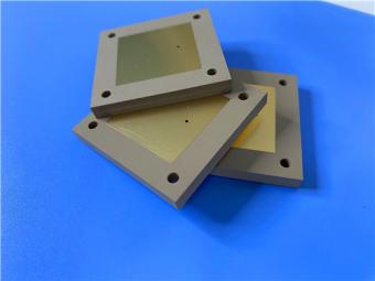
Rogers TMM10 PCB 5.08mm Core ENIG 2-Layer High-Dk Microwave Board
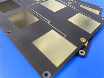
Taconic TLX-8 PCB 50mil ENIG 2-Layer High-Frequency RF Circuit Board
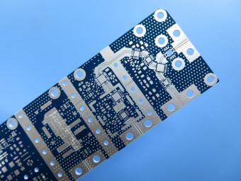
RO4003C exhibit a stable dielectric constant over a broad frequency range. This makes it an ideal substrate for broadband applications. And signal integrity performance improvement over the stack-ups with all FR4 board.
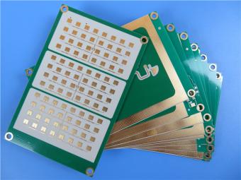
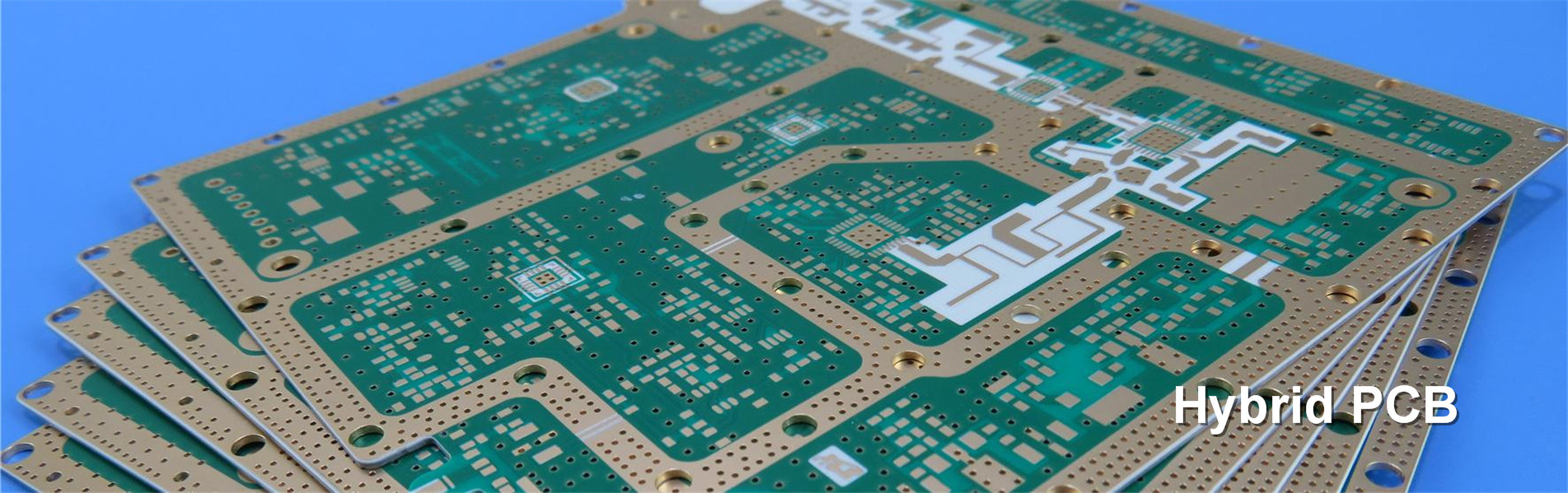
The hybrid PCB can be a mixture of FR-4 and high frequency material, and a mixture of high frequency material with different dielectric constant (DK)
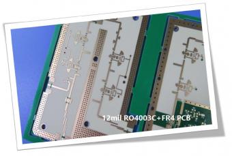
The 12mil core is on the top layer and it mainly plays the roles of signal layer. The core has fixed thickness which is very important to the electrical length of RF lines on the circuit board.
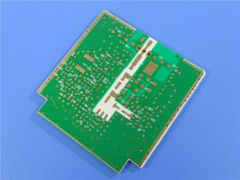
The hybrid PCB can be a mixture of FR-4 and high frequency material as abovementioned.
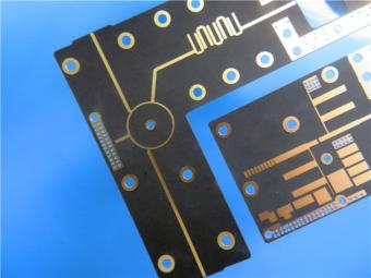
It contains 2 different boards in the panel. PCB boards are manufactured strictly as per required specifications with the standard IPC-Class-II.
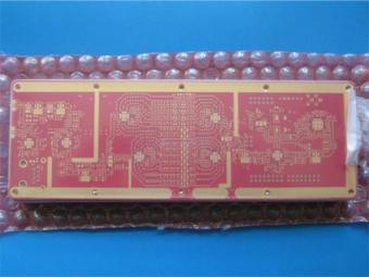
Hybrid PCB is also known as mixed material lamination, it’s normally combined by two different material like FR4 and PI(rigid flex PCB), FR4 and Ceramic, FR4 and Teflon, FR4 and Aluminum base etc.
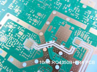
Hybrid constructions PCB typically involve a low loss material such as Nelco or Rogers combined with another core material like FR-4.
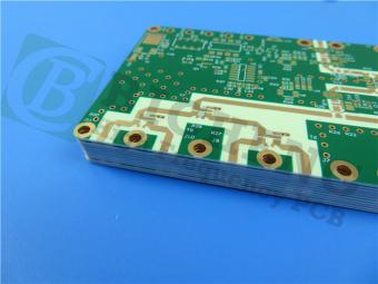
The Hybrid PCB on RO3003 and High Tg FR-4 is a state-of-the-art solution for high-frequency applications. With its exceptional stability, reliability, and manufacturability, it caters to the demands of industries such as automotive, telecommunications, and satellite communications.
 6-11C Shidai Jingyuan, Fuyong, Baoan, Shenzhen, Guangdong, China 518103


For inquiries about our products or pricelist, please leave to us and we will be in touch within 24 hours.
© Copyright: 2026 Shenzhen Bicheng Electronics Technology Co., Ltd.. All Rights Reserved.

IPv6 network supported


