
 Call Us Now !
Tel : +86 755 27374946
 Order Online Now !
Email : info@bichengpcb.com
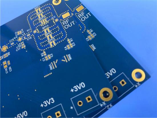
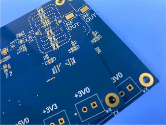
This 6-layer RO3003 + 370HR hybrid PCB is an engineered compromise in the best sense: 5 mil ceramic-filled PTFE on the RF layers for low, stable dielectric behavior, high-Tg FR-4 on the body for thermal and assembly reliability, and a controlled 0.82 mm thin build with L1–L2 blind vias, copper-paste via plugging and ENIG.
Item NO.:
BIC-637-v721Order(MOQ):
1-10Payment:
T/TProduct Origin:
ChinaShipping Port:
ShenzhenLead Time:
7-10 days
6-Layer 5mil Rogers RO3003 Mixed-Laminated with Isola 370HR 0.82mm Hybrid PCB with ENIG
This 6-layer hybrid circuit board is built for RF and microwave modules that cannot compromise between high-frequency electrical performance and high-volume manufacturing reliability. The top sub-stack uses a 5 mil (0.127 mm) Rogers RO3003 ceramic-filled PTFE core between layers 1 and 2, where the controlled-impedance RF lines and antenna feeds are routed. The remaining multilayer body is built from Isola 370HR high-Tg epoxy cores and PCL370HR prepreg, a lead-free compatible FR-4 system qualified for sequential lamination and multiple reflow cycles.
The finished board is pressed to a nominal 0.82 mm, with 1 oz copper on the outer layers and 0.5 oz copper on the inner layers, an electroless nickel immersion gold (ENIG) finish, blue solder mask and white legend. Interconnects combine L1–L2 blind vias in the RF section with 0.15 mm through vias plugged with copper paste, giving designers short ground-return paths, planar SMT pads and a thermally robust ground network. Every board is 100% electrical tested against the net list before shipment.
· True high-frequency sub-stack: 5 mil RO3003 with dielectric constant 3.00 and dissipation factor 0.0010 at 10 GHz, supporting designs up to millimeter-wave bands.
· High-reliability FR-4 body: 370HR with Tg 180 °C, Td 340 °C and proven CAF resistance for lead-free assembly.
· Controlled thin build: three 5 mil cores and two 0.149 mm prepreg bonds pressed to a nominal 0.82 mm total thickness.
· Advanced interconnects: L1–L2 blind vias plus 0.15 mm through vias plugged with copper paste.
· ENIG surface finish, blue solder mask with white legend, and 100% net-list electrical test on every board.
Table 1 summarizes the construction, materials, finish and quality provisions of the6-layer hybrid board as manufactured.
Table 1. PCB Construction Details
|
Item |
Specification |
|
Base material |
Hybrid mixed lamination: Rogers RO3003 (ceramic-filled PTFE) + Isola 370HR high-Tg FR-4, bonded with PCL370HR prepreg |
|
Layer count |
6 layers |
|
Board dimensions |
83 mm × 42 mm = 1 PCS |
|
Finished (pressed) thickness |
0.82 mm nominal (stack-up calculation 0.821 mm) |
|
Finished copper weight |
1 oz (35 µm) outer layers; 0.5 oz (18 µm) inner layers |
|
Blind vias |
Yes — L1 to L2 blind vias, located in the RO3003 RF sub-stack |
|
Through vias |
0.15 mm diameter |
|
Via filling |
0.15 mm through vias plugged with copper paste |
|
Surface finish |
ENIG (Electroless Nickel Immersion Gold) |
|
Solder mask |
Blue, top and bottom |
|
Silkscreen / legend |
White, top and bottom |
|
Electrical test |
100% electrical test prior to shipment |
Table 2 details the layer-by-layer dielectric and copper build, which sums to the 0.821 mm nominal pressed thickness shown in Figure 1.
Table 2. PCB Stack-Up (Layer Sequence and Thickness)
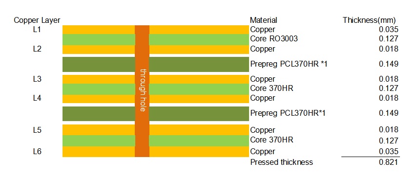
Figure 1.6-layer RO3003 + 370HR hybrid stack-up.
Rogers 3003 is a ceramic-filled PTFE composite whose primary job in this stack is signal fidelity. Its dielectric constant is held at 3.00 plus or minus 0.04 (process value at 10 GHz) and its dissipation factor is only 0.0010 at 10 GHz, an order of magnitude below general-purpose FR-4. The dielectric constant is exceptionally stable with temperature — a thermal coefficient of −3 ppm/°C from −50 to 150 °C — and remains flat across frequency, which keeps filter response and antenna resonance predictable over temperature and bandwidth; Rogers reports the laminate can be used in applications up to 77 GHz. On a 5 mil core, 50 Ω microstrip lines and tightly controlled differential pairs are narrow and well defined, so the thin dielectric both supports precise impedance control and keeps the RF sub-stack compact.
The Isola370HR epoxy body does a different job. With a Tg of 180 °C, Td of 340 °C, T288 time-to-delamination of 30 minutes and documented conductive anodic filament (CAF) resistance, it survives lead-free reflow and sequential pressing without the handling and processing constraints of an all-PTFE board. Its in-plane CTE of 13/14 ppm/°C is close to the 17/16 ppm/°C of RO3003, which helps the two resin systems coexist through thermal cycling. Using RO3003 only on the RF layers and 370HR on the power, control and digital layers avoids the cost premium and processing risk of an all-PTFE construction while preserving the electrical performance where it matters. This division of labor is the reason hybrid stacks have become the mainstream build for medium-volume RF modules: measured millimeter-wave performance on the critical layers, and FR-4 economics on the rest.
At 0.82 mm, this is a thin6-layer board, and the thickness budget is tightly defined. Three 5 mil (0.127 mm) cores contribute 0.381 mm, two PCL370HR prepreg bonds contribute 0.149 mm each after lamination, and the six copper layers (outer 1 oz, inner 0.5 oz) contribute 0.142 mm, giving the nominal pressed thickness of 0.821 mm. Because resin flow shifts the final prepreg thickness, the press program uses controlled glass styles and resin content together with measured core thicknesses to hold the nominal, which in turn protects the impedance values engineered on the RO3003 layer.
PTFE does not flow and bond the way epoxy does, and the z-axis expansion behavior differs sharply: RO3003 lists a z-axis CTE of about 25 ppm/°C, while 370HR expands at 45 ppm/°C below Tg and 230 ppm/°C above Tg. Lamination therefore uses a segmented ramp-and-soak profile with staged vacuum and pressure, rather than a single fast heat cycle, to let the epoxy fully wet the PTFE surface and cool without locked-in residual stress. PTFE-exposed holes and copper interfaces receive plasma or equivalent desmear preparation before metallization, because a conventional FR-4 desmear alone will not activate PTFE. These steps are the practical defense against delamination and innerlayer separation at the material interface.
L1–L2 blind vias add a sequential or controlled-depth drilling step, so inner-layer pad registration and the blind-to-inner-land alignment are controlled as first-article dimensions rather than balanced on the line later. Thin multilayer boards are also sensitive to bow and twist: the build is geometrically balanced in dielectric thickness around the center, copper distribution is equalized on the two outer layers, and post-lamination stress-relief baking holds flatness for SMT. The 0.15 mm through vias are plugged with copper paste to deliver a void-free, planar fill for pad-on-via assembly and a continuous electrical and thermal path to the ground planes; fill quality is verified by cross-section inspection.
The L1–L2 blind vias are deliberately placed in the RO3003 sub-stack. In RF layouts, a short blind via to the adjacent reference plane gives the lowest-inductance return path without the long via stub that a through-hole connection would leave through a6-layer board — a measurable advantage at the frequencies where RO3003 operates. ENIG provides a flat, coplanar pad surface suitable for fine-pitch and SMT assembly, with the gold layer protecting the nickel barrier from oxidation and supporting multiple reflow passes.
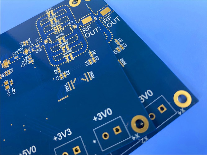
Combining the 77 GHz capability of RO3003 with the lead-free assembly robustness of 370HR, this hybrid PCB build is suited to:
This 6-layer RO3003 + 370HR hybrid PCB is an engineered compromise in the best sense: 5 mil ceramic-filled PTFE on the RF layers for low, stable dielectric behavior, high-Tg FR-4 on the body for thermal and assembly reliability, and a controlled 0.82 mm thin build with L1–L2 blind vias, copper-paste via plugging and ENIG. For RF modules that need millimeter-wave-ready electrical performance without the cost and processing overhead of an all-PTFE board, the construction is a repeatable, production-qualified answer rather than a prototype-only stack.
Part II — CCL Material Knowledge Guide: Rogers RO3003 and Isola 370HR
A copper-clad laminate (CCL) is the dielectric-and-copper base from which PCBs are patterned. In a hybrid board, two CCL systems with different resin chemistry share one pressed panel. The guide below presents the two materials independently, using the manufacturer typical-value data that drive the design decisions in Part I; each section can be read on its own.
RO3003 is a member of the Rogers RO3000 series, a family of ceramic-filled PTFE composite circuit materials intended for commercial microwave and RF applications. The ceramic filler loading is tuned so that mechanical properties remain consistent across the dielectric-constant range, which lets designers combine different dielectric materials in one multilayer board without introducing warpage or reliability problems. The in-plane CTE of 17 ppm/°C (x) and 16 ppm/°C (y) is matched to copper, giving excellent dimensional stability — typical etch shrinkage after etch and bake is below 0.5 mil per inch — while the low z-axis CTE supports plated-through-hole reliability even in severe thermal environments. The laminate is fabricated with standard PTFE circuit-board processing and is explicitly suitable for epoxy-glass hybrid multilayer designs, which is exactly how it is used in this board.
Its distinguishing electrical features are low dielectric loss, a dielectric constant that is stable versus both temperature and frequency, and uniform mechanical properties across Dk grades. Rogers identifies band-pass filters, microstrip patch antennas and voltage-controlled oscillators as ideal applications, alongside automotive radar and satellite antennas.
Table 3 lists the complete typical property set of RO3003 from the manufacturer standard properties table, including electrical, thermal, mechanical and physical data.
Table 3. RO3003 Typical Properties (Complete Manufacturer Data Sheet Set)
|
Property |
Typical Value |
Test Conditions |
Test Method |
|
Dielectric constant (process) |
3.00 ± 0.04 |
23 °C, 10 GHz |
IPC-TM-650 2.5.5.5 |
|
Dielectric constant (design) |
3.00 |
8–40 GHz |
Differential phase length |
|
Dissipation factor |
0.0010 |
23 °C, 10 GHz |
IPC-TM-650 2.5.5.5 |
|
Thermal coefficient of Dk |
−3 ppm/°C |
−50 to 150 °C, 10 GHz |
IPC-TM-650 2.5.5.5 |
|
Volume resistivity |
10⁷ MΩ·cm |
Condition A |
IPC-TM-650 2.5.17.1 |
|
Surface resistivity |
10⁷ MΩ |
Condition A |
IPC-TM-650 2.5.17.1 |
|
Decomposition temperature (Td) |
500 °C |
TGA |
ASTM D3850 |
|
CTE, x-axis |
17 ppm/°C |
−55 to 288 °C, 23 °C / 50% RH |
IPC-TM-650 2.4.41 |
|
CTE, y-axis |
16 ppm/°C |
−55 to 288 °C, 23 °C / 50% RH |
IPC-TM-650 2.4.41 |
|
CTE, z-axis |
25 ppm/°C |
−55 to 288 °C, 23 °C / 50% RH |
IPC-TM-650 2.4.41 |
|
Thermal conductivity |
0.50 W/(m·K) |
50 °C |
ASTM D5470 |
|
Copper peel strength |
12.7 lb/in (≈ 2.2 N/mm) |
1 oz ED copper, after solder float |
IPC-TM-650 2.4.8 |
|
Young's modulus |
930 / 823 MPa |
23 °C, length / cross direction |
ASTM D638 |
|
Dimensional stability (MD / CMD) |
−0.06 / +0.07 mm/m |
Condition A |
IPC-TM-650 2.2.4 |
|
Flammability |
V-0 |
- |
UL 94 |
|
Moisture absorption |
0.04% |
D48/50 |
IPC-TM-650 2.6.2.1 |
|
Density |
2.1 g/cm³ |
23 °C |
ASTM D792 |
|
Specific heat capacity |
0.9 J/(g·K) |
- |
Calculated |
|
Lead-free process compatible |
Yes |
- |
- |
Standard configurations: RO3003 is supplied in thicknesses of 0.005 in (0.13 mm) ± 0.0005 in, 0.010 in (0.25 mm), 0.020 in (0.51 mm), 0.030 in (0.76 mm) and 0.060 in (1.52 mm); on 12 × 18 in and 24 × 18 in panels (24 × 21 in also available for the 5 and 10 mil gauges); with electrodeposited or rolled copper foil in 1/2 oz (18 µm) and 1 oz (35 µm). The 5 mil core used in this board is the thinnest standard gauge, reinforcing its suitability for compact, controlled-impedance RF sub-stacks.
370HR, designed by Polyclad and branded PCL-FR-370HR, is built on a patented high-performance 180 °C Tg multifunctional epoxy resin system for multilayer printed wiring boards where maximum thermal performance and reliability are required. It is manufactured with high-quality E-glass fabric for superior conductive anodic filament (CAF) resistance, and combines low CTE with mechanical, chemical and moisture resistance that equal or exceed traditional FR-4. Isola positions 370HR as best-in-class among lead-free compatible products; the system is qualified to IPC-4101 slash sheets /98, /99, /101 and /126 and UL File E41625, and is RoHS compliant.
From a fabrication standpoint, 370HR is FR-4 process compatible, provides UV blocking and AOI fluorescence, is multiple-reflow capable, and is compatible with HDI technology and sequential lamination — a direct fit for a6-layer board with L1–L2 blind vias. Laminate is offered from 2 to 125 mil (0.05 to 3.2 mm) with HTE Grade 3, reverse-treat (RTF) or embedded-resistor foil in 1/2, 1 and 2 oz (18, 35 and 70 µm), and prepreg is available in E-glass, square-weave and mechanically spread fabrics.
Table 4 lists the complete typical-value set of 370HR laminate and laminated prepreg from the manufacturer data sheet, covering thermal, electrical, mechanical and safety properties.
Table 4. Isola 370HR Typical Values (Complete Manufacturer Data Sheet Set)
|
Property |
Typical Value |
Units |
Test Method (IPC-TM-650 unless noted) |
|
Glass transition temperature (Tg), DSC |
180 |
°C |
2.4.25C |
|
Decomposition temperature (Td), TGA, 5% weight loss |
340 |
°C |
2.4.24.6 |
|
Time to delamination T260 / T288 |
60 / 30 |
min |
2.4.24.1 |
|
Z-axis CTE, pre-Tg |
45 |
ppm/°C |
2.4.24C |
|
Z-axis CTE, post-Tg |
230 |
ppm/°C |
2.4.24C |
|
Total z-axis expansion, 50–260 °C |
2.8 |
% |
2.4.24C |
|
X/Y-axis CTE, pre-Tg |
13 / 14 |
ppm/°C |
2.4.24C |
|
Thermal conductivity |
0.4 |
W/(m·K) |
ASTM E1952 |
|
Thermal stress, 10 s @ 288 °C |
Pass (unetched & etched) |
- |
2.4.13.1 |
|
Dk @ 100 MHz / 1 GHz / 2 GHz / 5 GHz / 10 GHz |
4.24 / 4.17 / 4.04 / 3.92 / 3.92 |
- |
2.5.5.3 / 2.5.5.9 / Bereskin stripline |
|
Df @ 100 MHz / 1 GHz / 2 GHz / 5 GHz / 10 GHz |
0.0150 / 0.0161 / 0.0210 / 0.0250 / 0.0250 |
- |
2.5.5.3 / 2.5.5.9 / Bereskin stripline |
|
Volume resistivity (after moisture / at elevated temp.) |
3.0×10⁸ / 7.0×10⁸ |
MΩ·cm |
2.5.17.1 |
|
Surface resistivity (after moisture / at elevated temp.) |
3.0×10⁶ / 2.0×10⁸ |
MΩ |
2.5.17.1 |
|
Dielectric breakdown |
>50 |
kV |
2.5.6B |
|
Arc resistance |
115 |
s |
2.5.1B |
|
Electric strength |
54 (1350) |
kV/mm (V/mil) |
2.5.6.2A |
|
Comparative tracking index (CTI) |
PLC 3 (175–249) |
class (V) |
UL 746A / ASTM D3638 |
|
Peel strength |
1.14–1.25 (6.5–7.0) |
N/mm (lb/in) |
2.4.8C / 2.4.8.2A / 2.4.8.3 |
|
Flexural strength, length / cross |
620 / 531 |
MPa |
2.4.4B |
|
Tensile strength, length / cross |
385 / 245 |
MPa |
ASTM D3039 |
|
Young's modulus, length / cross |
3744 / 3178 |
ksi |
ASTM D790-15e2 |
|
Poisson's ratio, length / cross |
0.177 / 0.171 |
- |
ASTM D3039 |
|
Moisture absorption |
0.15 |
% |
2.6.2.1A |
|
Flammability |
V-0 |
rating |
UL 94 |
|
Relative thermal index (RTI) |
130 |
°C |
UL 796 |
Table 5 places the key properties side by side; the two materials occupy different positions on the dielectric-loss, thermal and process maps.
Table 5. RO3003 versus 370HR — Key CCL Property Comparison
|
Property |
Rogers RO3003 |
Isola 370HR |
|
Resin system |
Ceramic-filled PTFE composite |
Multifunctional epoxy (FR-4) |
|
Dk at 10 GHz |
3.00 |
3.92 |
|
Df at 10 GHz |
0.0010 |
0.0250 |
|
Tg (DSC) |
Not applicable (PTFE matrix) |
180 °C |
|
Td (TGA) |
500 °C |
340 °C |
|
X / Y CTE |
17 / 16 ppm/°C |
13 / 14 ppm/°C |
|
Z-axis CTE |
25 ppm/°C |
45 / 230 ppm/°C (pre / post-Tg) |
|
Thermal conductivity |
0.50 W/(m·K) |
0.40 W/(m·K) |
|
Moisture absorption |
0.04% |
0.15% |
|
Processing |
PTFE process; hybrid-compatible |
Standard FR-4 process |
|
Primary role in this board |
RF / antenna layers (L1–L2) |
Structural, power and digital layers (L3–L6) |
The two materials are not competitors in this design. RO3003 trades a higher material price and PTFE processing for exceptionally low, frequency-stable loss; 370HR trades a measure of loss margin for FR-4 familiarity, high Tg, CAF resistance and lower unit cost. Their closely matched in-plane CTE and the documented hybrid compatibility of RO3003 are what make the mix manufacturable rather than experimental.
Choosing a CCL is choosing the electrical and thermal envelope of the finished board. RO3003 brings a near-temperature-invariant dielectric constant, a 0.0010 dissipation factor and usability up to 77 GHz to the layers that carry RF signals, while 370HR brings an 180 °C Tg, 340 °C Td, proven CAF resistance and standard FR-4 manufacturability to the layers that carry everything else. For designers, the rule is simple: specify the high-frequency material only on the layers whose performance budget demands it, and let a qualified high-Tg FR-4 do the rest. The hybrid stack then delivers both the measured electrical performance and the unit cost that a volume RF product needs — which is precisely the balance the 6-layer board in Part I is built around.

If you have questions or suggestions,please leave us a message,we will reply you as soon as we can!
Categories
New Products
6-Layer 5mil Rogers RO3003 Mixed-Laminated with Isola 370HR 0.82 mm Hybrid PCB with ENIG
4-Layer 8mil RO4003C + Tg170 FR-4 Hybrid PCB with ENIG — 0.556mm Thin Build
1100 × 350mm Long-Format Rogers RO4003C 32 mil core Double-Sided High-Frequency PCB
Wangling TP2200 PCB 0.8mm Substrate Immersion Gold 2-Layer High-Dk (Dk 22) RF Board
Rogers TMM10 PCB 5.08mm Core ENIG 2-Layer High-Dk Microwave Board
Taconic TLX-8 PCB 50mil ENIG 2-Layer High-Frequency RF Circuit Board
Wangling TF440 25mil DK4.4 Laminate Immersion Gold 2-Layer Copper-filling Vias PCB
RO4360G2 Rogers 12mil ENEPIG 2-Layer DK6.15 High Frequency Custom PCB
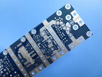
RO4003C exhibit a stable dielectric constant over a broad frequency range. This makes it an ideal substrate for broadband applications. And signal integrity performance improvement over the stack-ups with all FR4 board.
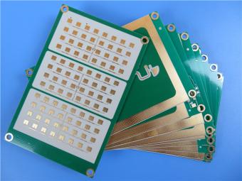
The hybrid PCB can be a mixture of FR-4 and high frequency material, and a mixture of high frequency material with different dielectric constant (DK)
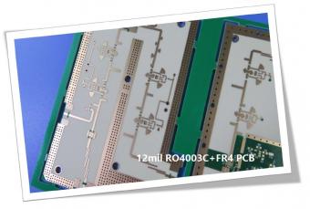
The 12mil core is on the top layer and it mainly plays the roles of signal layer. The core has fixed thickness which is very important to the electrical length of RF lines on the circuit board.
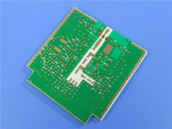
The hybrid PCB can be a mixture of FR-4 and high frequency material as abovementioned.
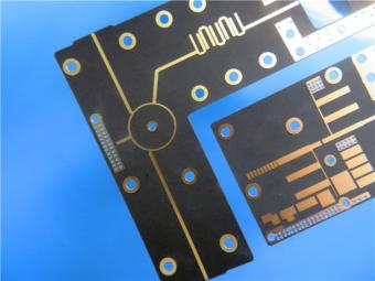
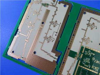
It contains 2 different boards in the panel. PCB boards are manufactured strictly as per required specifications with the standard IPC-Class-II.
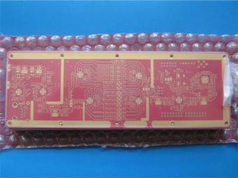
Hybrid PCB is also known as mixed material lamination, it’s normally combined by two different material like FR4 and PI(rigid flex PCB), FR4 and Ceramic, FR4 and Teflon, FR4 and Aluminum base etc.
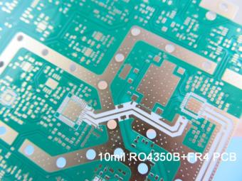
Hybrid constructions PCB typically involve a low loss material such as Nelco or Rogers combined with another core material like FR-4.
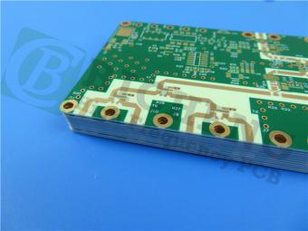
The Hybrid PCB on RO3003 and High Tg FR-4 is a state-of-the-art solution for high-frequency applications. With its exceptional stability, reliability, and manufacturability, it caters to the demands of industries such as automotive, telecommunications, and satellite communications.
 6-11C Shidai Jingyuan, Fuyong, Baoan, Shenzhen, Guangdong, China 518103


For inquiries about our products or pricelist, please leave to us and we will be in touch within 24 hours.
© Copyright: 2026 Shenzhen Bicheng Electronics Technology Co., Ltd.. All Rights Reserved.

IPv6 network supported


