
 Call Us Now !
Tel : +86 755 27374946
 Order Online Now !
Email : info@bichengpcb.com
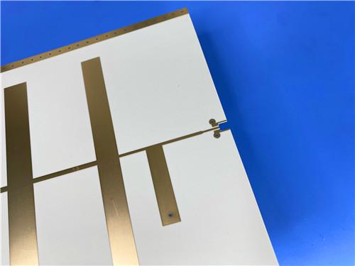
This Long-Format Rogers RO4003C PCB is a purpose-built RF platform rather than a generic double-sided panel
Item NO.:
BIC-635-v719Order(MOQ):
1-10Payment:
T/TProduct Origin:
ChinaShipping Port:
ShenzhenLead Time:
7-10 days
1100 × 350mm Long-Format Rogers RO4003C 32 mil core Double-Sided High-Frequency PCB
32 mil (0.813 mm) core | 1 oz finished copper, both outer layers | Immersion Gold (ENIG), 2 μin gold | 1 PCS
Product description — high-frequency / RF antenna substrate
When an RF antenna, power-divider network or sensor array is longer than a standard fabrication panel, the usual response is to split the design into several sub-boards and join them with connectors, cable assemblies or soldered transitions. Every such joint is a penalty: added insertion loss, intermodulation products, phase and amplitude mismatch between sections, and an additional point of failure in the field.
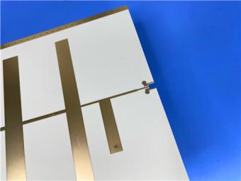
This product takes the opposite route. It is a single-piece,double-sided high-frequency PCB built on Rogers RO4003C hydrocarbon ceramic laminate and delivered as one continuous 1100 mm × 350 mm panel (1 PCS). A 32 mil (0.813 mm) core, 1 oz finished copper on both outer layers and an electroless nickel/immersion gold (ENIG) surface with 2 μin gold combine to give a low-loss, mechanically stable substrate that maintains signal integrity over the full 1.1 metre length.
The format and finish are deliberately matched to large radiating structures rather than to general-purpose control boards. Typical end uses include cellular base-station and sector antennas, long slot and patch arrays, corporate feed and power-divider networks, RFID and beam-forming structures, low-noise block (LNB) down-converters for direct-broadcast satellite, and automotive radar and sensor assemblies.
With no solder mask and no silkscreen over the conductors, every controlled-impedance trace and radiating element sits in a single, well-defined dielectric environment — the construction RF antenna designers prefer when they need repeatable impedance, predictable radiation patterns and the lowest practical insertion loss.
Table 1 summarises the controlled manufacturing parameters of this build, defining the material, format, copper, surface finish and test basis used for production.
|
Item |
Specification |
|
Base material |
Rogers RO4003C woven-glass-reinforced hydrocarbon / ceramic laminate (not PTFE) |
|
Layer count |
Double sided (2-layer), no inner layers, no blind/buried vias |
|
Board dimensions |
1100 mm × 350 mm = 1 PCS (oversized / long-format single panel) |
|
Finished board thickness |
0.813 mm (32 mil) dielectric core |
|
Finished copper weight |
1 oz — 35 μm (1.4 mil) nominal — on both outer layers |
|
Surface finish |
Immersion Gold (ENIG), gold thickness 2 μin over electroless nickel barrier |
|
Top silkscreen |
None |
|
Bottom silkscreen |
None |
|
Top solder mask |
None |
|
Bottom solder mask |
None |
|
Electrical test |
100% electrical test (open / short / continuity) prior to shipment |
Table 1. PCB construction details for the 1100 × 350 mm RO4003C board.
Table 2 sets out the symmetric two-metal-layer stack: a single 0.813 mm RO4003C core is clad on both faces with 1 oz copper and protected by ENIG, with no dielectric coating on either side.
|
Layer |
Build / material |
Role in the design |
|
Layer 1 — Top (outer copper) |
1 oz finished Cu, 35 μm (1.4 mil) nominal; ENIG, 2 μin gold |
Radiating elements, controlled-impedance / feed lines and contact pads |
|
Core dielectric |
Rogers RO4003C, 0.813 mm (32 mil) nominal; Dk 3.38 ± 0.05 @ 10 GHz |
Low-loss, dimensionally stable hydrocarbon / ceramic core (1080 / 1674 glass styles) |
|
Layer 2 — Bottom (outer copper) |
1 oz finished Cu, 35 μm (1.4 mil) nominal; ENIG, 2 μin gold |
Ground / reference plane and secondary circuitry |
Table 2. Double-sided stackup. No solder mask or silkscreen is applied to either face; the Rogers 32 mil dielectric gauge is supplied to ±0.0020 in (±0.051 mm).
Five design and fabrication decisions define the electrical and mechanical behaviour of this board.
Rogers supplies Rogers 4003C in panels up to 48 × 36 in (1219 × 915 mm). A 1100 mm long axis therefore fits within a single genuine laminate sheet, so the board is produced from continuous material rather than from edge-joined or butted sub-panels. There is no splice crossing the radiating aperture, no connector pair interrupting a feed line, and no change in dielectric lot or copper treatment from one end of the array to the other. For the customer this means fewer parts to procure and assemble, one continuous reference plane, and tighter amplitude and phase matching across long multi-element arrays.
Solder mask is a second dielectric. Applied over a microstrip antenna or a controlled-impedance feed, it shifts the effective dielectric constant, adds frequency-dependent loss, and introduces tolerances from coating thickness and moisture uptake that are difficult to simulate. Leaving both faces uncoated removes these variables: the electromagnetic fields see only the RO4003C core and air, exactly as modelled. ENIG then protects the exposed copper with a thin, planar, noble-metal surface — 2 μin immersion gold over an electroless nickel barrier. The result is flat pad geometry suited to fine features and to contact or wire bonding, long shelf life with good oxidation resistance and consistent solderability, without the thickness variation of organic finishes.
RO4003C substrate is specified with a process dielectric constant of 3.38 ± 0.05 at 10 GHz and a design Dk of 3.55 across 8–40 GHz, while its dissipation factor is only 0.0027 at 10 GHz and 0.0021 at 2.5 GHz. The dielectric constant is therefore both tightly controlled and comparatively flat over the bands used by microwave antennas, and its thermal coefficient is just +40 ppm/°C from −50 °C to 150 °C. On a board more than a metre long, where small per-unit-length errors accumulate, that stability means impedance and resonant-frequency targets set at room temperature remain valid across the operating temperature range rather than drifting from one end of the panel to the other.
The laminate's coefficient of thermal expansion is 11, 14 and 46 ppm/°C in the X, Y and Z axes respectively; the in-plane values are close to copper, which underwrites the reported dimensional stability of <0.3 mm/m after etching and thermal cycling. A low Z-axis expansion supports reliable plated through holes under thermal shock. A glass transition temperature above 280 °C and a decomposition temperature of 425 °C keep the board stable through lead-free assembly, and a copper peel strength of 1.05 N/mm (6 pli) retains fine traces and pads. Moisture absorption of only 0.06% is particularly relevant for outdoor antenna hardware exposed to humidity.
Although RO4003C delivers PTFE-grade microwave performance, it is a rigid, thermoset, woven-glass-reinforced hydrocarbon/ceramic laminate that processes on standard epoxy/glass (FR-4) equipment. It does not require the sodium-etch or specialised through-hole preparation that PTFE materials demand, it is compatible with automated handling and scrubbing, and it is lead-free assembly compatible and CAF resistant. These characteristics keep conversion cost and lead time predictable even at an oversized panel. Before shipment, every board passes 100% electrical test for opens, shorts and continuity, so a single large panel arrives as a known-good unit rather than carrying an untested section.
· RF front ends — Cellular base-station antennas and power amplifiers
· Antenna arrays — Large slot, patch and phased-array antennas and corporate feed / power-divider networks
· Identification — RFID antennas and reader boards
· Sensing — Automotive radar and sensor substrates
· Satellite — LNBs for direct-broadcast satellite and other microwave front ends
This Long-Format Rogers RO4003C PCB is a purpose-built RF platform rather than a generic double-sided panel: a genuine one-piece1100 × 350 mm RO4003C laminate, a controlled 32 mil (0.813 mm) core, 1 oz copper on both faces, a flat 2 μin ENIG finish, and no solder mask or silkscreen to perturb the RF field.
The combination of long-format continuous construction, low and stable dielectric loss, copper-matched thermal expansion and full electrical test addresses the specific failure modes of large antennas — splice loss, phase mismatch, finish variation and latent opens — while remaining manufacturable on standard FR-4 lines. For designers scaling an antenna or feed network beyond ordinary panel dimensions, it offers a single, continuous, well-characterised substrate with fully documented material performance.
Part 2 — Copper Clad Laminate (CCL) Knowledge: Rogers RO4003C
The electrical performance of the board above is set by the laminate beneath it. Rogers RO4003C is a proprietary woven-glass-reinforced hydrocarbon/ceramic laminate engineered to deliver the high-frequency performance of PTFE/woven-glass materials while retaining the manufacturability of conventional epoxy/glass (FR-4). It is not a PTFE-based material. The resin system is filled with ceramic and reinforced with glass fabric, and it is offered in configurations using both 1080 and 1674 glass styles, all of which meet the same electrical performance specification. This part documents the laminate independently of the finished board so it can be used as a standalone material-selection reference.
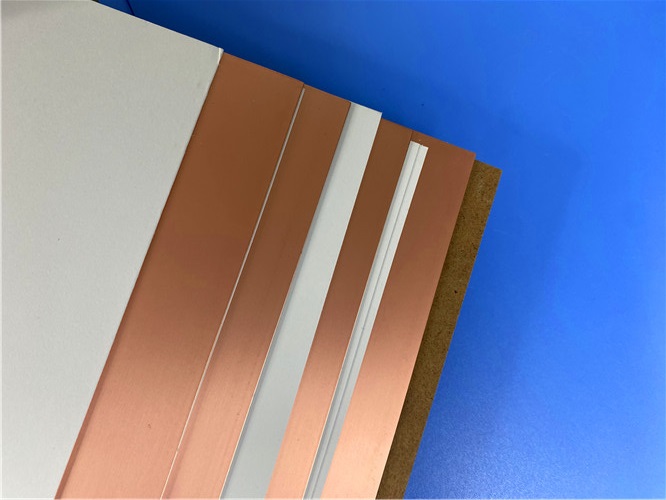
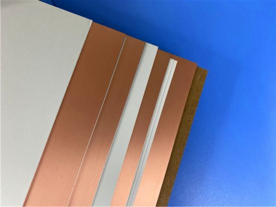
Figure 1. Rogers RO4003C high-frequency copper clad laminate (CCL) panels, shown as bare copper-clad stock before circuit fabrication.
RO4003C pairs a tightly controlled dielectric constant with low loss while using the same processing route as standard epoxy/glass, but at a fraction of the cost of conventional microwave laminates. Unlike PTFE-based microwave materials, it requires no special through-hole treatments or handling procedures. It is a rigid, thermoset laminate suited to automated handling and copper-surface scrubbing equipment, which makes it attractive for performance-sensitive, high-volume builds and for multilayer constructions. The material is non-brominated and is not UL 94 V-0 rated; for designs that require a UL 94 V-0 flame rating, RO4350B or RO4835 laminates should be considered instead. RO4003C conforms to the requirements of IPC-4103, slash sheet /10, and is documented as lead-free process compatible and CAF resistant.
Table 3 consolidates the published typical property set for RO4003C — electrical, mechanical, thermal and physical — with test conditions and methods. Values are typical of the production population; for specification limits designers should consult Rogers Corporation.
|
Property |
Typical value |
Dir. |
Units |
Condition / test method |
|
Dielectric constant, εr (process) |
3.38 ± 0.05 |
Z |
— |
10 GHz / 23 °C; IPC-TM-650 2.5.5.5 clamped stripline |
|
Dielectric constant, εr (design) |
3.55 |
Z |
— |
8–40 GHz; differential phase length method |
|
Dissipation factor, tan δ |
0.0027 / 0.0021 |
Z |
— |
10 GHz / 2.5 GHz, 23 °C; IPC-TM-650 2.5.5.5 |
|
Thermal coefficient of εr |
+40 |
Z |
ppm/°C |
−50 to 150 °C; IPC-TM-650 2.5.5.5 |
|
Volume resistivity |
1.7 × 10¹⁰ |
— |
MΩ·cm |
Cond A; IPC-TM-650 2.5.17.1 |
|
Surface resistivity |
4.2 × 10⁹ |
— |
MΩ |
Cond A; IPC-TM-650 2.5.17.1 |
|
Electrical strength |
31.2 (780) |
Z |
kV/mm (V/mil) |
0.51 mm (0.020 in) sample; IPC-TM-650 2.5.6.2 |
|
Tensile modulus |
19,650 / 19,450 (2,850 / 2,821) |
X / Y |
MPa (ksi) |
RT; ASTM D638 |
|
Tensile strength |
139 / 100 (20.2 / 14.5) |
X / Y |
MPa (ksi) |
RT; ASTM D638 |
|
Flexural strength |
276 (40) |
— |
MPa (kpsi) |
IPC-TM-650 2.4.4 |
|
Dimensional stability |
<0.3 |
X, Y |
mm/m (mils/in) |
After etch + E2/150 °C; IPC-TM-650 2.4.39A |
|
Coefficient of thermal expansion |
11 / 14 / 46 |
X / Y / Z |
ppm/°C |
−55 to 288 °C; IPC-TM-650 2.4.41 |
|
Tg (glass transition) |
>280 |
— |
°C (TMA) |
IPC-TM-650 2.4.24.3 |
|
Td (decomposition) |
425 |
— |
°C (TGA) |
ASTM D3850 |
|
Thermal conductivity |
0.71 |
— |
W/m·K |
80 °C; ASTM C518 |
|
Moisture absorption |
0.06 |
— |
% |
48 h immersion, 0.060 in sample, 50 °C; ASTM D570 |
|
Density |
1.79 |
— |
g/cm³ |
23 °C; ASTM D792 |
|
Copper peel strength |
1.05 (6.0) |
— |
N/mm (pli) |
After solder float, 1 oz EDC foil; IPC-TM-650 2.4.8 |
|
Flammability |
Not rated (non-brominated) |
— |
— |
UL 94 — not V-0; use RO4350B / RO4835 for V-0 |
|
Lead-free process compatible |
Yes |
— |
— |
— |
Table 3. RO4003C typical properties (Rogers RO4000 series data sheet, PUB 92-004).
Table 4 lists the standard RO4003C gauges, panel formats and claddings; the 32 mil (0.813 mm) core and 1 oz copper used on the featured board are standard, stocked configurations.
|
Category |
Standard offering |
Note |
|
Dielectric thicknesses |
0.008 in (0.203 mm) ±0.0010 0.012 in (0.305 mm) ±0.0010 0.016 in (0.406 mm) ±0.0015 0.020 in (0.508 mm) ±0.0015 0.032 in (0.813 mm) ±0.0020 ← this build 0.060 in (1.524 mm) ±0.0040 |
Non-standard gauges from 0.0066–0.060 in by increment |
|
Standard panel sizes |
24 × 18 in (610 × 457 mm) 24 × 21 in (610 × 533 mm) 24 × 36 in (610 × 915 mm) 48 × 36 in (1219 × 915 mm) |
Additional panel sizes available; the 1100 mm long axis fits the 48 × 36 in sheet |
|
Copper claddings |
Electrodeposited copper foil ½ oz (18 μm) HH/HH 1 oz (35 μm) H1/H1 ← this build |
Additional cladding weights and LoPro reverse-treated foil available |
Table 4. Standard RO4003C configurations.
The three charts below illustrate the advantages that drive antenna selection: a dielectric constant that stays nearly constant with temperature, a Dk that is stable over frequency, and low microstrip insertion loss.
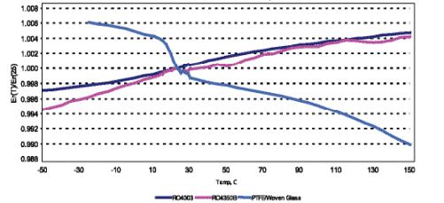
Figure 2. Dielectric constant vs. temperature — RO4003C remains essentially flat across −50 to 150 °C, where PTFE/woven glass shows a pronounced downward slope.
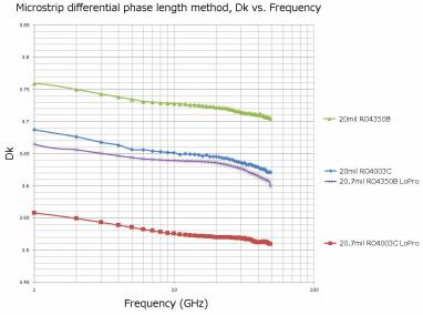
Figure 3. Dielectric constant vs. frequency (microstrip differential phase length method) for RO4003C and comparison materials.
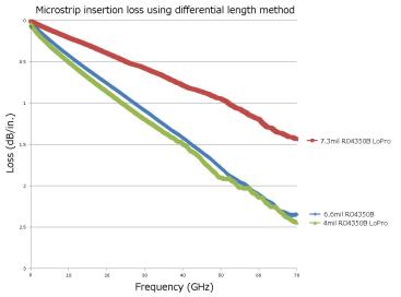
Figure 4. Microstrip insertion loss vs. frequency — the RO4003C curve (6.5 mil RO4350B / 4 mil RO4350B LoPro family shown for comparison) supports low-loss broadband designs.
Rogers laminates are evaluated under NASA test procedure SP-R-0022A, in which 100–300 mg specimens (etched free of copper) are heated under vacuum at 125 °C for 24 hours with a collector held at 25 °C. Materials showing Total Mass Loss (TML) below 1.0% and Collected Volatile Condensable Materials (CVCM) below 0.1% are classified as low-outgassing and suitable for space use. RO4003C comfortably meets both limits, as shown in Table 5, supporting satellite and aerospace antenna use such as direct-broadcast LNBs.
|
Material |
Total Mass Loss (TML) % |
Collected volatiles (CVCM) % |
Water vapour recovered (WVR) % |
|
RO4003C |
0.06 |
0.00 |
0.02 |
|
RO4350B (for reference) |
0.12 |
0.02 |
0.02 |
|
NASA low-outgassing limit |
< 1.0 |
< 0.1 |
Reporting optional |
Table 5. NASA SP-R-0022A outgassing results at 125 °C, ≤10⁻⁶ torr.
· Processes like FR-4: rigid thermoset laminate compatible with standard epoxy/glass fabrication, automated handling and scrubbing; no sodium-etch or special via preparation required.
· Lead-free assembly compatible and CAF resistant; high Tg (>280 °C) keeps expansion stable across circuit processing temperatures.
· LoPro reverse-treated foil is available for reduced insertion loss; it adds approximately 0.0007 in (18 μm) per core and uses a modified resin with a resin Dk of about 2.4.
· Non-brominated and not UL 94 V-0; specify RO4350B or RO4835 where a V-0 flame rating is mandatory.
· Conforms to IPC-4103 slash sheet /10; typical values represent population averages and specification limits should be confirmed with Rogers.
RO4003C occupies a deliberate position in the high-frequency laminate market: PTFE-class dielectric constant and loss, a Dk that is stable with both frequency and temperature, copper-matched thermal expansion, documented low outgassing, and the processing economics of FR-4. Its 32 mil (0.813 mm) gauge and 1 oz cladding are standard, stocked configurations, while its largest 48 × 36 in panel size directly enables the single-piece 1100 × 350 mm board described in Part 1. For non-flame-rated RF and antenna designs it is a well-supported, cost-effective and manufacturing-friendly choice; where a UL 94 V-0 rating is mandatory, RO4350B or RO4835 should be selected instead.

If you have questions or suggestions,please leave us a message,we will reply you as soon as we can!
Categories
New Products
1100 × 350mm Long-Format Rogers RO4003C 32 mil core Double-Sided High-Frequency PCB
Wangling TP2200 PCB 0.8mm Substrate Immersion Gold 2-Layer High-Dk (Dk 22) RF Board
Rogers TMM10 PCB 5.08mm Core ENIG 2-Layer High-Dk Microwave Board
Taconic TLX-8 PCB 50mil ENIG 2-Layer High-Frequency RF Circuit Board
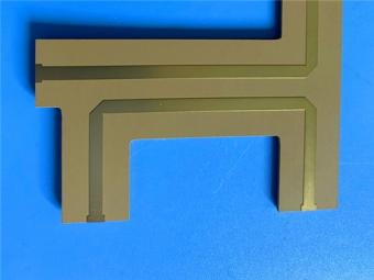
Wangling TF440 25mil DK4.4 Laminate Immersion Gold 2-Layer Copper-filling Vias PCB
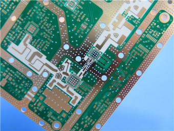
RO4360G2 Rogers 12mil ENEPIG 2-Layer DK6.15 High Frequency Custom PCB
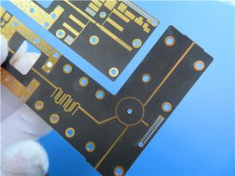
Wangling F4BTMS220 2-Layer DK2.2 PCB 10 mil Core with Immersion Gold
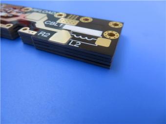
Wangling F4BTME350 10mil DK3.5 High Frequency Substrate PCB 2-Layer Immersion Gold
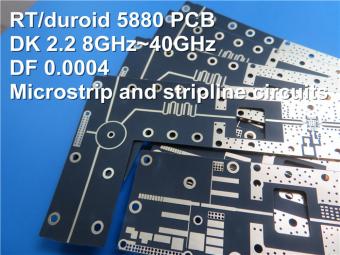
This is a type of double sided RF PCB built on RT/duroid 5880 for the application of Radar Systems.
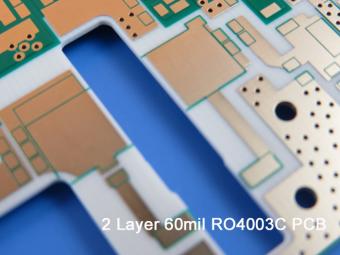
RO4003C PCBs are hydrocarbon ceramic filled laminates, not PTFE which are designed to offer superior high frequency performance.
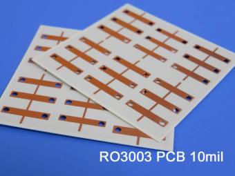
Rogers RO3003 high frequency circuit materials are ceramic-filled PTFE composites intended for use in commercial microwave and RF applications. It was designed to offer exceptional electrical and mechanical stability at competitive prices.
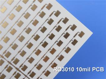
RO3010 laminates are competitively priced products with exceptional mechanical and electrical stability. This stability simplifies the design of broadband components and allows the materials to be used in a wide range of applications over a very broad range of frequencies.
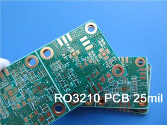
These RO3210 materials are engineered to offer exceptional electrical performance and mechanical stability. RO3210 laminates combine the surface smoothness of a non-woven PTFE laminate.
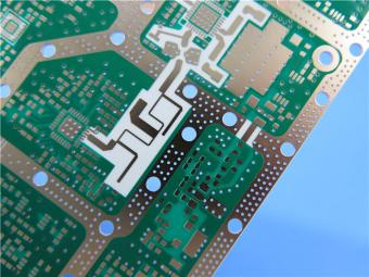
RT/duroid 6035HTC laminates are an exceptional choice for high power applications.
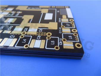
TC350 is designed to provide enhanced heat-transfer through “Best-In-Class” thermal conductivity, while reducing dielectric loss and insertion loss. Lower losses result in higher Amplifier and Antenna Gains/Efficiencies.
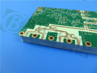
RO3035 materials exhibit a coefficient of thermal expansion(CTE) in the X and Y axis of 17 ppm/℃. This expansion coefficient is matched to that of copper, which allows the material to exhibit excellent dimensional stability.
 6-11C Shidai Jingyuan, Fuyong, Baoan, Shenzhen, Guangdong, China 518103


For inquiries about our products or pricelist, please leave to us and we will be in touch within 24 hours.
© Copyright: 2026 Shenzhen Bicheng Electronics Technology Co., Ltd.. All Rights Reserved.

IPv6 network supported


