

 Call Us Now !
Tel : +86 755 27374946
Call Us Now !
Tel : +86 755 27374946
 Order Online Now !
Email : info@bichengpcb.com
Order Online Now !
Email : info@bichengpcb.com
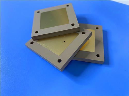
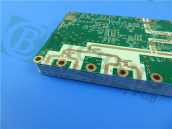
The TMM10 PCB 5.08mm Core ENIG is a focused microwave board: two-layer, single-core construction on a controlled 9.20 Dk laminate, a thick 200 mil core, 1 oz copper and a flat ENIG finish, with no mask or silkscreen to disturb the RF field.
Item NO.:
BIC-633-v717Order(MOQ):
1-10Payment:
T/TProduct Origin:
ChinaShipping Port:
ShenzhenLead Time:
7-10 days
Rogers TMM10 PCB 5.08mm Core ENIG 2-Layer High-Dk Microwave Board
Product Description & TMM10 CCL Material Guide
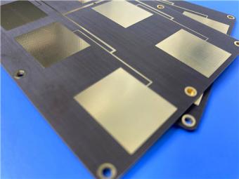
The TMM10 PCB 5.08mm Core ENIG is a two-layer rigid microwave board built on Rogers TMM10, a ceramic-filled thermoset laminate with a 9.20 Dk at 10 GHz. Its 5.08 mm (200 mil) core is clad with 1 oz copper and finished with ENIG; with no mask/silkscreen, two nets and 100% testing, it serves high-frequency antennas where a stable high-Dk dielectric matters more than routing density.
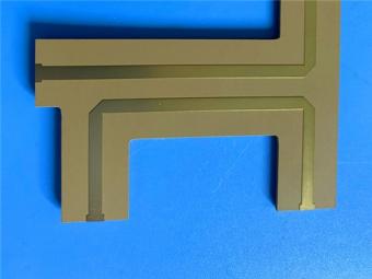
A dedicated microwave substrate rather than a general-purpose board, its 63.9 × 48 mm outline, single 200 mil core and two copper layers suit planar RF circuits with a high controlled Dk: GPS and patch antennas, satellite feeds, dielectric polarizers, chip testers and stripline/microstrip structures.
The table below summarizes the as-built construction from base material to finish and inspection.
Table 1. PCB construction details.
|
Parameter |
Specification |
|
Base material |
Rogers TMM10 |
|
Layer count |
2, double sided |
|
Board dimensions |
63.9 × 48 mm, 1 PCS, ±0.15 mm |
|
Minimum trace / space |
4 / 7 mil |
|
Minimum hole size |
0.25 mm |
|
Blind / buried vias |
None |
|
Finished board thickness |
5.1 mm |
|
Finished copper weight |
1 oz (35 µm) |
|
Via plating thickness |
20 µm |
|
Surface finish |
ENIG |
|
Top silkscreen |
No |
|
Bottom silkscreen |
No |
|
Top solder mask |
No |
|
Bottom solder mask |
No |
|
Electrical test |
100% tested |
|
Artwork format |
Gerber RS-274-X |
|
Quality standard |
IPC Class 2 |
|
Availability |
Worldwide |
The board carries no solder mask or silkscreen, since a polymer mask would add a dielectric layer over the traces, shifting Dk and adding loss; bare ENIG pads keep only the TMM10 core in the signal path. It is qualified to IPC Class 2 and 100% electrically tested.
The two-layer stackup places the RF network on a single, homogeneous5.08 mm TMM10 core.
Table 2. Two-layer PCB stackup.
|
Layer |
Material |
Thickness |
|
Copper Layer 1 (top) |
Electrodeposited copper |
35 µm |
|
Core |
Rogers TMM10 |
5.08 mm (200 mil) |
|
Copper Layer 2 (bottom) |
Electrodeposited copper |
35 µm |
|
Finished board thickness |
— |
5.1 mm (nominal) |
The 200 mil core is one of the thickest standards in the TMM10 range; the 5.1 mm board is the core plus two 35 µm copper layers. A thick high-Dk core raises the Dk seen by a radiator, shortening the guided wavelength and shrinking the antenna footprint, and a deep uniform dielectric for polarizers and cavity fixtures.
The statistics describe a compact, single-sided RF assembly on two nets.
Table 3. PCB statistics.
|
Parameter |
Value |
|
Components |
26 |
|
Total pads |
38 |
|
Thru-hole pads |
21 |
|
Top SMT pads |
17 |
|
Bottom SMT pads |
0 |
|
Vias |
13 |
|
Nets |
2 |
ENIG gives a flat, planar surface and durable protection: a nickel barrier under immersion gold provides good solderability for the 17 SMT pads and through-hole terminations and resists oxidation. The thermoset core does not soften in assembly, so pads stay bonded, and the board is 100% tested for continuity and isolation.
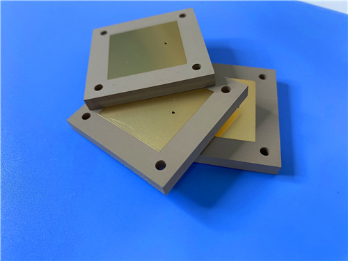
The TMM10 high frequency PCB is a focused microwave board: two-layer, single-core construction on a controlled 9.20 Dk laminate, a thick 200 mil core, 1 oz copper and a flat ENIG finish, with no mask or silkscreen to disturb the RF field. It is a purpose-built platform for compact antennas, satellite and GPS circuits and dielectric-loaded components, with full electrical verification.
Part 1 covered the board; this part covers the underlying CCL: composition, data sheet, forms and applications.
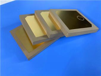
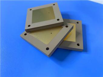
Rogers TMM10 substrate is a ceramic-filled hydrocarbon thermoset composite designed for high-reliability plated-through-hole stripline/microstrip circuits. It combines ceramic-like electrical behavior with the ease of soft laminates: a high Dk, low loss, copper-matched CTE, no sodium napthanate treatment prior to plating, and resistance to creep, cold flow and chemicals. It does not soften when heated, so wire bonding proceeds without pad lifting and lead-free assembly is supported; it is clad with electrodeposited copper foil.
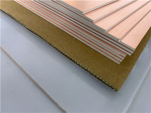
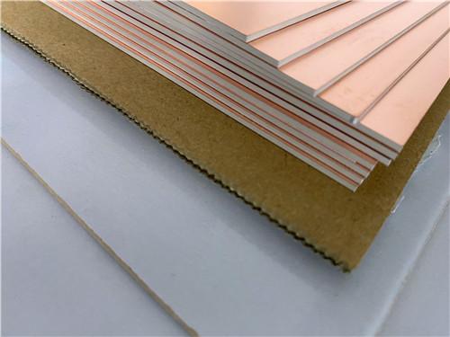
Figure 1. Copper-clad TMM10 laminate
The completeTMM10 data sheet follows.
Table 4. TMM10 complete data sheet (typical values; not specification limits). Source: Rogers TMM10 data sheet, publication 92-108.
|
Property |
Condition |
Typical Value |
Unit |
Test Method |
|
ELECTRICAL PROPERTIES |
||||
|
Dk (process) |
10 GHz, Z |
9.20 ± 0.230 |
— |
IPC 2.5.5.5 |
|
Dk (design) |
8–40 GHz |
9.8 |
— |
Differential Phase |
|
Dissipation Factor |
10 GHz, Z |
0.0022 |
— |
IPC 2.5.5.5 |
|
TCDk |
−55–125 °C |
−38 |
ppm/°K |
IPC 2.5.5.5 |
|
Insulation Resistance |
C/96/60/95 |
>2000 |
GΩ |
ASTM D257 |
|
Volume Resistivity |
— |
2 × 10⁸ |
MΩ·cm |
ASTM D257 |
|
Surface Resistivity |
— |
4 × 10⁷ |
MΩ |
ASTM D257 |
|
Dielectric Strength |
Z |
285 |
V/mil |
IPC 2.5.6.2 |
|
THERMAL PROPERTIES |
||||
|
Td (decomposition) |
TGA |
425 |
°C |
ASTM D3850 |
|
CTE — X |
0–140 °C |
21 |
ppm/K |
ASTM E831 |
|
CTE — Y |
0–140 °C |
21 |
ppm/K |
ASTM E831 |
|
CTE — Z |
0–140 °C |
20 |
ppm/K |
ASTM E831 |
|
Thermal Conductivity |
Z, 80 °C |
0.76 |
W/m/K |
ASTM C518 |
|
MECHANICAL PROPERTIES |
||||
|
Peel Strength (thermal stress) |
1 oz Cu, float |
5.0 (0.9) |
lb/in (N/mm) |
IPC 2.4.8 |
|
Flexural Strength |
X, Y |
13.62 |
kpsi |
ASTM D790 |
|
Flexural Modulus |
X, Y |
1.79 |
Mpsi |
ASTM D790 |
|
PHYSICAL PROPERTIES |
||||
|
Moisture Absorption |
1.27 mm, D/24/23 |
0.09 |
% |
ASTM D570 |
|
Moisture Absorption |
3.18 mm, D/24/23 |
0.20 |
% |
ASTM D570 |
|
Specific Gravity |
— |
2.77 |
— |
ASTM D792 |
|
Specific Heat Capacity |
— |
0.74 |
J/g/K |
Calculated |
|
Lead-Free Compatible |
— |
Yes |
— |
— |
Typical values, not specification limits; confirm critical parameters with Rogers.
TMM10's key design payoff is miniaturization: guided wavelength scales with 1/√Dk, so a radiator on TMM10 occupies roughly 1/√9.8, about 32% of the linear dimension of an air radiator and 67% of one on 4.4-Dk FR-4 — why it replaces alumina-class substrates. Its 0.0022 loss, −38 ppm/°K thermal coefficient, insulation resistance above 2000 GΩ and 285 V/mil strength preserve performance across temperature.
Isotropic CTE of 21, 21 and 20 ppm/K in x, y and z closely matches copper, giving plated barrels low thermal-cycling stress and reliable PTHs. The 425 °C Td and lead-free compatibility give ample soldering margin, while the 0.76 W/m/K conductivity is about twice that of PTFE/ceramic laminates, aiding heat removal, and peel strength of 5.0 lb/in confirms the foil adheres.
TMM10 is available across a broad thickness range, standard sizes and two weights.
Table 5. TMM10 standard thicknesses, panel sizes and claddings.
|
Parameter |
Available Form |
|
Dielectric thickness |
0.015–0.500 in (0.381–12.70 mm), ±0.0015 in |
|
Standard thicknesses |
0.015–0.200 in (12 increments); 0.250, 0.500 in |
|
Standard panel sizes |
18 × 12 in (457 × 305 mm); 18 × 24 in (457 × 610 mm) |
|
Standard claddings |
1/2 oz (18 µm) or 1 oz (35 µm) ED Cu |
|
Other forms |
Heavy-metal cladding, unclad; extra sizes |
TMM10 serves the RF, antenna, aerospace and test systems.
TMM10 high frequency laminate is a differentiated ceramic-filled thermoset laminate: a 9.20 process Dk (9.8 design), 0.0022 loss, a −38 ppm/°K thermal coefficient, copper-matched CTE, 425 °C Td and roughly twice the conductivity of PTFE/ceramic substrates. It offers ceramic-like behavior with soft-board processing, no sodium napthanate treatment and reliable wire bonding — the basis of its use in compact antennas and dielectric-loaded circuits.





If you have questions or suggestions,please leave us a message,we will reply you as soon as we can!
Categories
New Products
Wangling TP2200 PCB 0.8mm Substrate Immersion Gold 2-Layer High-Dk (Dk 22) RF Board
Rogers TMM10 PCB 5.08mm Core ENIG 2-Layer High-Dk Microwave Board
Taconic TLX-8 PCB 50mil ENIG 2-Layer High-Frequency RF Circuit Board
Wangling TF440 25mil DK4.4 Laminate Immersion Gold 2-Layer Copper-filling Vias PCB
RO4360G2 Rogers 12mil ENEPIG 2-Layer DK6.15 High Frequency Custom PCB

Wangling F4BTMS220 2-Layer DK2.2 PCB 10 mil Core with Immersion Gold

Wangling F4BTME350 10mil DK3.5 High Frequency Substrate PCB 2-Layer Immersion Gold

Wangling F4BTM300 Custom 2-layer PCB 20mil DK3.0 Substrate with Immersion Gold
This is a type of double sided RF PCB built on RT/duroid 5880 for the application of Radar Systems.
RO4003C PCBs are hydrocarbon ceramic filled laminates, not PTFE which are designed to offer superior high frequency performance.
Rogers RO3003 high frequency circuit materials are ceramic-filled PTFE composites intended for use in commercial microwave and RF applications. It was designed to offer exceptional electrical and mechanical stability at competitive prices.
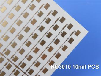
RO3010 laminates are competitively priced products with exceptional mechanical and electrical stability. This stability simplifies the design of broadband components and allows the materials to be used in a wide range of applications over a very broad range of frequencies.
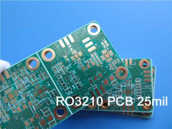
These RO3210 materials are engineered to offer exceptional electrical performance and mechanical stability. RO3210 laminates combine the surface smoothness of a non-woven PTFE laminate.
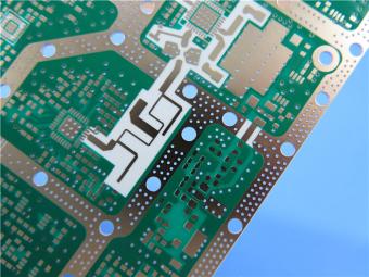
RT/duroid 6035HTC laminates are an exceptional choice for high power applications.
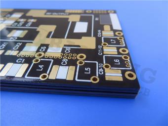
TC350 is designed to provide enhanced heat-transfer through “Best-In-Class” thermal conductivity, while reducing dielectric loss and insertion loss. Lower losses result in higher Amplifier and Antenna Gains/Efficiencies.
RO3035 materials exhibit a coefficient of thermal expansion(CTE) in the X and Y axis of 17 ppm/℃. This expansion coefficient is matched to that of copper, which allows the material to exhibit excellent dimensional stability.
 6-11C Shidai Jingyuan, Fuyong, Baoan, Shenzhen, Guangdong, China 518103


For inquiries about our products or pricelist, please leave to us and we will be in touch within 24 hours.
© Copyright: 2026 Shenzhen Bicheng Electronics Technology Co., Ltd.. All Rights Reserved.

IPv6 network supported


