

 Call Us Now !
Tel : +86 755 27374946
Call Us Now !
Tel : +86 755 27374946
 Order Online Now !
Email : info@bichengpcb.com
Order Online Now !
Email : info@bichengpcb.com
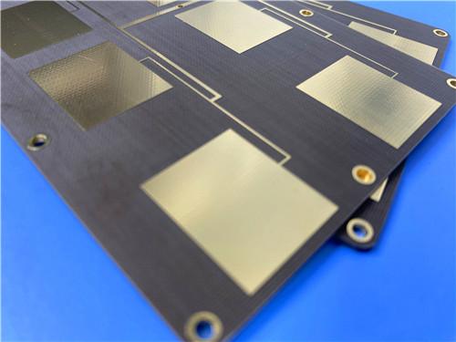

The TLX-8 PCB 50mil ENIG is a focused, well-specified RF board: a two-layer, single-core construction on a controlled 2.55 Dk laminate, 1 oz copper and a flat ENIG finish, with no solder mask or silkscreen to disturb the microwave performance.
Item NO.:
BIC-632-v717Order(MOQ):
1-10Payment:
T/TProduct Origin:
ChinaShipping Port:
ShenzhenLead Time:
7-10 days
Taconic TLX-8 PCB 50mil ENIG 2-Layer High-Frequency RF Circuit Board
Product Description & TLX-8 CCL Material Guide
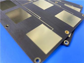
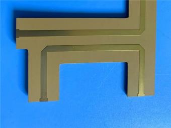
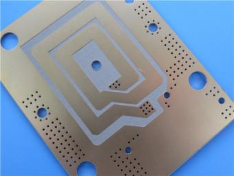
The TLX-8 PCB 50mil ENIG is a two-layer rigid radio-frequency circuit board built on Taconic TLX-8, a PTFE woven-fiberglass microwave laminate. A single 50 mil (1.27 mm) dielectric core is clad on both sides with 1 oz copper and finished with electroless nickel/immersion gold (ENIG), leaving the RF surface flat, protected and solderable. Designed for low-layer-count microwave networks, the board carries a compact antenna-style feed layout with 13 components on two nets, is built to IPC Class 2 and is 100% electrically tested before shipment.
This Taconic board is a purpose-built RF substrate rather than a general-purpose multilayer digital board. Its 45 × 66.04 mm outline, single 50 mil core and two copper layers suit planar microwave circuits that depend on a controlled, uniform dielectric between the signal and reference planes. The low dielectric constant of Taconic TLX-8 PCB(2.55 at 10 GHz) supports controlled-impedance structures in a compact antenna feed network. The construction is deliberately simple — two layers, no blind or buried vias and a single-sided component layout — which keeps the RF path predictable and supports consistent high-volume production.
The table below summarizes the as-built construction of the board, from the base laminate to the surface finish and final inspection.
|
Parameter |
Specification |
|
Base material |
Taconic TLX-8 (PTFE woven fiberglass) |
|
Layer count |
2 |
|
Board dimensions |
45 × 66.04 mm (1 PCS), ±0.15 mm |
|
Minimum trace / space |
6 / 9 mil |
|
Minimum hole size |
0.4 mm |
|
Blind / buried vias |
None |
|
Finished board thickness |
1.3 mm |
|
Finished copper weight |
1 oz (1.4 mil), outer layers |
|
Via plating thickness |
20 µm |
|
Surface finish |
ENIG |
|
Top silkscreen |
No |
|
Bottom silkscreen |
No |
|
Top solder mask |
No |
|
Bottom solder mask |
No |
|
Electrical test |
100% tested prior to shipment |
|
Artwork format |
Gerber RS-274-X |
|
Quality standard |
IPC Class 2 |
|
Availability |
Worldwide |
Table 1. PCB construction details.
Two choices define this Taconic High Frequency PCB. First, it is supplied with no solder mask and no silkscreen on either face. For an RF antenna board this is deliberate: a polymer solder mask adds an extra dielectric layer over the copper whose thickness and Dk can vary, perturbing 50-ohm structures and adding passive intermodulation. Leaving the copper exposed and protecting it with ENIG preserves a uniform dielectric and a stable, low-PIM surface. Second, the board uses conservative, proven geometries — 6/9 mil trace and space, 0.4 mm holes and 20 µm plated via barrels — that remain comfortably manufacturable while retaining RF design margin.
The two-layer stackup places the entire RF network over a single, homogeneous 50 mil TLX-8 core.
|
Layer |
Material |
Thickness |
|
Copper Layer 1 (top) |
Electrodeposited copper |
35 µm |
|
Core |
Taconic TLX-8 |
1.27 mm (50 mil) |
|
Copper Layer 2 (bottom) |
Electrodeposited copper |
35 µm |
|
Finished board thickness |
— |
1.3 mm (nominal) |
Table 2. Two-layer PCB stackup.
A single-core stackup suits low-layer-count microwave designs. The 1.27 mm (50 mil) TLX-8 core provides a consistent 2.55 Dk dielectric across the board, so the controlled-impedance features on top reference a continuous ground plane below, with no intermediate prepreg or bonding films to introduce dielectric variation. The 35 µm (1 oz) copper on each face matches the finished copper weight and gives a robust conductor for RF current, plus mechanical strength for the plated through-holes. The result is a finished board about 1.3 mm thick.
The statistics describe a compact, single-sided RF feed network built on just two nets.
|
Parameter |
Value |
|
Components |
13 |
|
Total pads |
26 |
|
Thru-hole pads |
12 |
|
Top SMT pads |
14 |
|
Bottom SMT pads |
0 |
|
Vias |
8 |
|
Nets |
2 |
Table 3. PCB statistics.
ENIG is specified for its flat, planar pad surface and durable protection. A thin nickel barrier covered by an immersion-gold layer gives excellent solderability for the SMT components, resists oxidation during storage and offers a smooth contact surface favourable for RF and low-PIM operation. Each board is fabricated from Gerber RS-274-X artwork to IPC Class 2, the widely accepted qualification for commercial and telecommunications electronics, and undergoes 100% electrical test before shipment to confirm continuity and isolation. Together with the conservative feature set, these controls support repeatable high-volume supply worldwide.
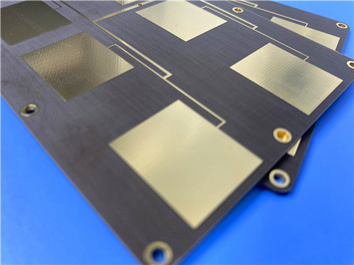
The TLX-8 PCB 50mil ENIG is a focused, well-specified RF board: a two-layer, single-core construction on a controlled 2.55 Dk laminate, 1 oz copper and a flat ENIG finish, with no solder mask or silkscreen to disturb the microwave performance. Its conservative geometries, single-sided assembly, IPC Class 2 qualification and 100% electrical test provide a dependable basis for antennas, couplers, amplifiers and similar low-layer-count microwave circuits, delivered worldwide.
Part 2 — CCL Material Knowledge: Taconic TLX-8
Part 1 described the finished board. This part examines the underlying copper-clad laminate (CCL): its composition, complete data sheet, available forms and applications.
Taconic TLX-8 is a polytetrafluoroethylene (PTFE) microwave laminate reinforced with woven fiberglass. The PTFE supplies the electrical performance — a very low dielectric constant, an extremely low loss tangent and minimal moisture uptake — while the woven glass fabric gives the otherwise soft polymer the stiffness, dimensional stability and handling strength a board requires.TLX-8substrate is offered across a Dk range of 2.45 to 2.65; the grade used here is the 2.55 material. Because it combines genuine microwave performance with practical manufacturability, TLX-8 is regarded as a workhorse RF substrate produced in high volumes for antenna applications.
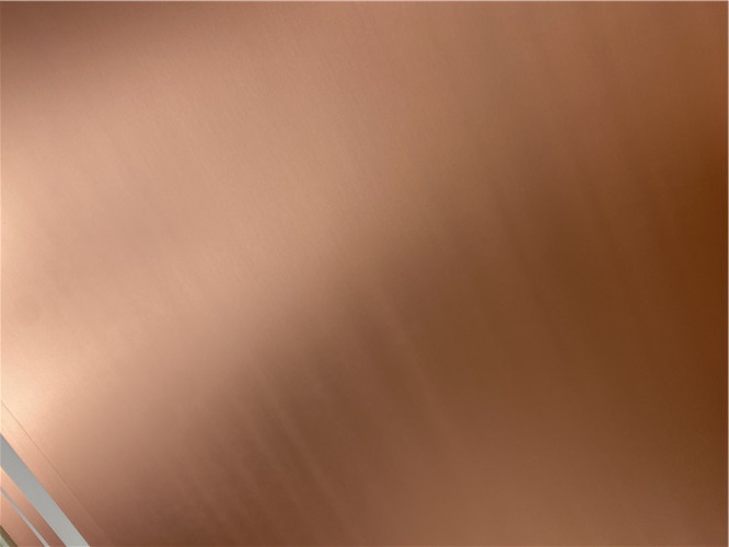
Figure 1. Copper-clad TLX-8 laminate: woven-fiberglass PTFE core with electrodeposited copper foil.
The fiberglass weave is the key to TLX-8 laminate in severe operating environments. Boards bolted to a housing and exposed to strong vibration during launch must resist creep; engine-mounted electronics see sustained high temperature; space hardware must tolerate radiation and meet low-outgassing limits; warship antennas face salt-laden conditions at sea; and altimeter substrates must track a wide temperature range in flight. In each case the woven reinforcement maintains alignment and bond integrity while the PTFE preserves electrical behaviour. TLX-8 consequently has a long heritage in space and defence programs wherever a mechanically reinforced, low-loss dielectric is required.
The following table presents the full set of typical TLX-8 properties, grouped by electrical, thermal, mechanical and physical characteristics, with the associated test methods.
|
Property |
Condition |
Typical Value |
Unit |
Test Method |
|
Electrical Properties |
||||
|
Dielectric Constant |
@ 10 GHz |
2.55 ± 0.04 |
— |
IPC-TM-650 2.5.5.3 |
|
Dissipation Factor |
@ 10 GHz |
0.0018 |
— |
IPC-TM-650 2.5.5.5.1 |
|
Outgassing, TML |
4 h, 257 °F, ≤5×10⁻⁵ Torr |
0.03 |
% |
ASTM E 595 |
|
Outgassing, CVCM |
4 h, 257 °F, ≤5×10⁻⁵ Torr |
0.00 |
% |
ASTM E 595 |
|
Outgassing, WVR |
4 h, 257 °F, ≤5×10⁻⁵ Torr |
0.01 |
% |
ASTM E 595 |
|
Surface Resistivity |
Elevated temperature |
6.605×10⁸ |
MΩ |
IPC-TM-650 2.5.17.1 |
|
Surface Resistivity |
Humidity conditioned |
3.550×10⁶ |
MΩ |
IPC-TM-650 2.5.17.1 |
|
Volume Resistivity |
Elevated temperature |
1.110×10¹⁰ |
MΩ·cm |
IPC-TM-650 2.5.17.1 |
|
Volume Resistivity |
Humidity conditioned |
1.046×10¹⁰ |
MΩ·cm |
IPC-TM-650 2.5.17.1 |
|
Dimensional Stability |
MD, after bake |
0.06 |
mm/M |
IPC-TM-650 2.4.39 |
|
Dimensional Stability |
CD, after bake |
0.08 |
mm/M |
IPC-TM-650 2.4.39 |
|
Dimensional Stability |
MD, thermal stress |
0.09 |
mm/M |
IPC-TM-650 2.4.39 |
|
Dimensional Stability |
CD, thermal stress |
0.10 |
mm/M |
IPC-TM-650 2.4.39 |
|
Thermal & Mechanical Properties |
||||
|
Thermal Conductivity |
— |
0.19 |
W/(m·K) |
ASTM F433 / ASTM 1530-06 |
|
CTE |
X, 25–260 °C |
21 |
ppm/°C |
IPC-TM-650 2.4.41 / ASTM D 3386 |
|
CTE |
Y, 25–260 °C |
23 |
ppm/°C |
IPC-TM-650 2.4.41 / ASTM D 3386 |
|
CTE |
Z, 25–260 °C |
215 |
ppm/°C |
IPC-TM-650 2.4.41 / ASTM D 3386 |
|
Decomposition Td |
2% weight loss |
535 |
°C |
IPC-TM-650 2.4.24.6 (TGA) |
|
Decomposition Td |
5% weight loss |
553 |
°C |
IPC-TM-650 2.4.24.6 (TGA) |
|
Peel Strength |
1 oz ED, thermal stress |
2.63 (15) |
N/mm (lb/in) |
IPC-TM-650 2.4.8 |
|
Peel Strength |
1 oz RTF, thermal stress |
2.98 (17) |
N/mm (lb/in) |
IPC-TM-650 2.4.8 |
|
Peel Strength |
½ oz ED, elevated temp |
2.45 (14) |
N/mm (lb/in) |
IPC-TM-650 2.4.8.3 |
|
Peel Strength |
½ oz ED, thermal stress |
1.93 (11) |
N/mm (lb/in) |
IPC-TM-650 2.4.8 |
|
Peel Strength |
1 oz rolled, thermal stress |
2.28 (13) |
N/mm (lb/in) |
IPC-TM-650 2.4.8 |
|
Young's Modulus |
MD |
6,757 (980) |
N/mm² (ksi) |
ASTM D 902 |
|
Young's Modulus |
CD |
8,274 (1,200) |
N/mm² (ksi) |
ASTM D 902 |
|
Young's Modulus |
MD |
11,238 (1,630) |
N/mm² (ksi) |
ASTM D 3039 |
|
Chemical / Physical Properties |
||||
|
Moisture Absorption |
— |
0.02 |
% |
IPC-TM-650 2.6.2.1 |
|
Dielectric Breakdown |
— |
> 45 |
kV |
IPC-TM-650 2.5.6 |
|
Flammability Rating |
— |
V-0 |
— |
UL 94 |
Table 4. TLX-8 complete data sheet (typical values; not specification limits). Source: Taconic/AGC TLX-8 data sheet.
All figures in Table 4 are typical values measured under the stated IPC-TM-650, ASTM or UL conditions, intended for design guidance rather than specification limits; customers should confirm critical tolerances directly.
These data explain why TLX-8 is favoured for antennas and passive RF networks. Its dielectric constant is tightly controlled at 2.55 ± 0.04 at 10 GHz, and its dissipation factor is just 0.0018, which translates directly into low insertion loss. Dk varies by only about ±2% from −55 to 125 °C, so circuits retain tuning over a wide thermal envelope; where still tighter stability is needed, a more temperature-stable grade such as TSM-DS3 can be considered. For base-station and shared-antenna designs, TLX-8 delivers excellent passive intermodulation behaviour, measured below −160 dBc on a PCB coupon at 20 W per channel over 800 and 1800 MHz. Its space pedigree is supported by NASA outgassing results of 0.03% TML and 0.00% CVCM per ASTM E 595, while 0.02% moisture absorption and a UL 94 V-0 rating complete the profile.
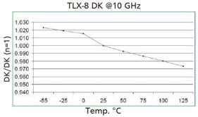
Figure 2. Normalized dielectric constant of TLX-8 versus temperature at 10 GHz (~±2% from −55 to 125 °C).
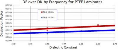
Figure 3. Dissipation factor versus dielectric constant for PTFE laminates at 1.9 and 10 GHz.
TLX-8 is produced across a dielectric thickness range of 0.0025 to 0.250 in (0.064 to 6.35 mm), in increments of 0.005 in (0.125 mm), with a choice of copper cladding types and weights. This breadth lets the same material family support thin feeding circuits as well as thick, rigid antenna panels. The standard panel is 18 × 24 in (457 × 610 mm), with additional sheet sizes available to order, as summarized below.
|
Parameter |
Available Form |
|
Dielectric thickness |
0.0025 – 0.250 in (0.064 – 6.35 mm) |
|
Thickness increment |
0.005 in (0.125 mm) |
|
Standard panel |
18 × 24 in (457 × 610 mm) |
|
Other sheet sizes |
12×18, 16×18, 16×36, 18×24, 18×48, 24×36, 36×48 inch |
Table 5. TLX-8 thicknesses and panel sizes.
Because of its low loss, stable Dk and mechanical durability, TLX-8 is used in radar systems, mobile communications infrastructure, microwave test equipment and transmission devices, and in RF components such as antennas, amplifiers, mixers, splitters, filters and combiners. It is particularly appropriate for low-layer-count microwave designs where a single, well-controlled dielectric is sufficient.
TLX-8 is a proven, high-volume PTFE/fiberglass microwave substrate that balances genuine electrical performance — a tightly controlled 2.55 Dk, a 0.0018 dissipation factor, low moisture uptake and excellent PIM — with the mechanical and thermal robustness needed in space, defence, marine and commercial antenna service. Its wide thickness and cladding options, fully documented property data and long flight heritage make it a dependable, cost-effective choice for low-layer-count RF designs and for the 50 mil ENIG board described above.





If you have questions or suggestions,please leave us a message,we will reply you as soon as we can!
Categories
New Products
Wangling TP2200 PCB 0.8mm Substrate Immersion Gold 2-Layer High-Dk (Dk 22) RF Board
Rogers TMM10 PCB 5.08mm Core ENIG 2-Layer High-Dk Microwave Board
Taconic TLX-8 PCB 50mil ENIG 2-Layer High-Frequency RF Circuit Board
Wangling TF440 25mil DK4.4 Laminate Immersion Gold 2-Layer Copper-filling Vias PCB
RO4360G2 Rogers 12mil ENEPIG 2-Layer DK6.15 High Frequency Custom PCB

Wangling F4BTMS220 2-Layer DK2.2 PCB 10 mil Core with Immersion Gold

Wangling F4BTME350 10mil DK3.5 High Frequency Substrate PCB 2-Layer Immersion Gold

Wangling F4BTM300 Custom 2-layer PCB 20mil DK3.0 Substrate with Immersion Gold
RF-35TC is a type of high frequency material from Taconic company. It offers a "best in class" low dissipation factor with high thermal conductivity.
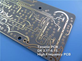
TLX offers reliability in a wide range of RF applications. This material is versatile due to its 2.45 - 2.65 DK range and available thicknesses and copper cladding. It is suitable for low layer count microwave designs.
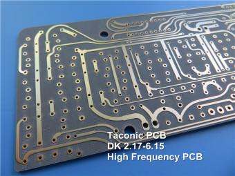
TLF-35A is another type of low cost RF material. It's the best choice for low cost, high volume commercial microwave and radio frequency applications.
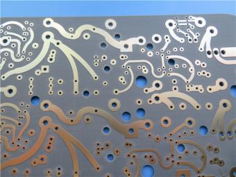
CER-10 is an organic-ceramic DK-10 laminate in the ORCER family of Taconic products. It is based on a woven glass reinforcement. CER-10 exhibits exceptional interlaminar bond strength and solder resistance.
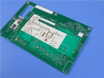
RO4360G2 laminates of Rogers Corporation are 6.15 Dk, low loss, glass-reinforced, hydrocarbon ceramic-filled thermoset materials that provide the ideal balance of performance and processing ease.
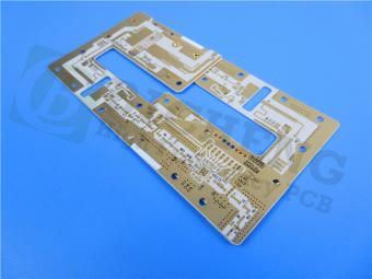
RF-60A is an organic-ceramic laminate in the ORganic CERamic(ORCER) family of Taconic products.
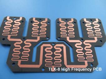
TLX is PTFE based fiberglass laminate, it is ideal for use in radar systems, mobile communications, microwave test equipment, microwave transmission devices and RF components.
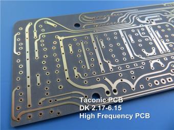
TLX offers reliability in a wide range of RF applications. This material is versatile due to its 2.45 - 2.65 DK range and available thicknesses and copper cladding. It is suitable for low layer count microwave designs
 6-11C Shidai Jingyuan, Fuyong, Baoan, Shenzhen, Guangdong, China 518103


For inquiries about our products or pricelist, please leave to us and we will be in touch within 24 hours.
© Copyright: 2026 Shenzhen Bicheng Electronics Technology Co., Ltd.. All Rights Reserved.

IPv6 network supported


