

 Call Us Now !
Tel : +86 755 27374946
Call Us Now !
Tel : +86 755 27374946
 Order Online Now !
Email : info@bichengpcb.com
Order Online Now !
Email : info@bichengpcb.com
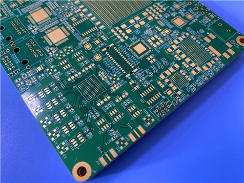
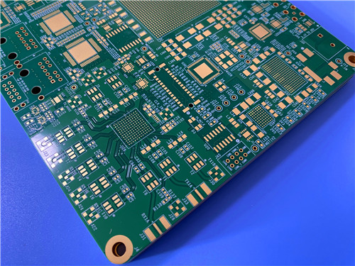
This 14-layer Megtron-6 ENEPIG PCB is a high-performance circuit board solution tailored for the most demanding high-speed, high-reliability applications.
Item NO.:
BIC-592-v677.0Order(MOQ):
1-10Payment:
T/TProduct Origin:
ChinaShipping Port:
ShenzhenLead Time:
7-10 days
14-layer Megtron-6 Panasonic high-speedLow-loss Substrate 1.64mm Thick PCB ENEPIG
1. Introduction
This 14-layer HDI printed circuit board (PCB) is engineered on Panasonic Megtron-6 ultra-low loss substrate platform, featuring an Electroless Nickel Electroless Palladium Immersion Gold (ENEPIG) surface finish, precision impedance control, and full compliance with IPC-3 industry standards. Designed for high-speed networking, 5G/6G wireless infrastructure, and industrial electronics applications, the board balances uncompromising signal integrity, thermal stability, and manufacturing reliability, with a symmetric 14-layer stackup optimized for controlled impedance and minimal high-frequency signal loss.
With a nominal finished thickness of 1.64mm, 2x2 panelization with process borders, and 100% electrical testing prior to shipment, this 14-layer Megtron-6 PCB delivers consistent, repeatable performance for both prototype validation and high-volume commercial deployments.
2.PCB Core Construction & Manufacturing Specifications
This section outlines the core mechanical, material, and manufacturing specifications that define the PCB’s physical dimensions, layer configuration, and adherence to global electronics industry standards, forming the structural foundation of the product.
|
Specification |
Value |
|
Base material |
Megtron-6 (Panasonic high-speed low-loss substrate) |
|
Layer count |
14 layers |
|
Board dimensions |
178.8×169mm (4PCS per panel), 2X2 panelization, 5mm width process border on all four sides |
|
Finished board thickness |
1.64mm (nominal; 1.641mm as pressed) |
|
Finished copper weight |
1oz (35μm) outer layers, 0.5oz (17μm) inner layers |
|
Resin filled via |
Compliant with IPC-4761 TYPE VII standard |
|
Manufacturing standard |
IPC-3 Standard |
|
Surface finish |
ENEPIG (Electroless Nickel Electroless Palladium Immersion Gold) |
|
Silkscreen |
White legend on both top and bottom sides |
|
Solder mask |
Green solder mask on both top and bottom sides |
|
Quality assurance |
100% electrical continuity and isolation test used prior to shipment |
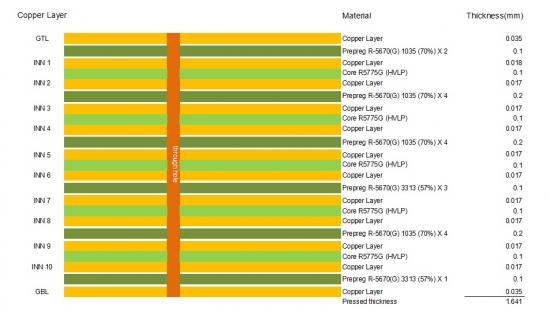
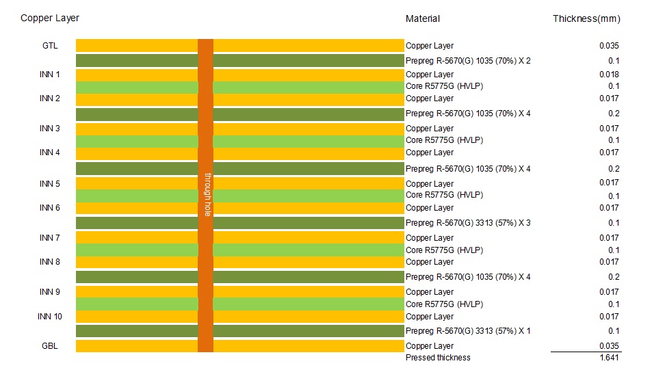
3.PCB Layer Stackup Design
The 14-layer stackup is symmetrically structured to ensure mechanical stability, consistent impedance control, and optimal signal integrity, with precisely selected core and prepreg materials that deliver the target finished board thickness while maintaining uniform dielectric properties across all layers.
4.Critical Performance Features
4.1 Precision Impedance Control
Precision impedance control is a non-negotiable design requirement for high-speed signal integrity, with strictly defined line width and spacing parameters for both microstrip and stripline configurations to meet target impedance values, validated against the Megtron-6 substrate’s dielectric properties.
|
Impedance Type |
Target Impedance |
Trace Width (mm) |
Trace Spacing (mm) |
|
Microstrip |
50Ω |
0.2 |
- |
|
Microstrip |
100Ω |
0.1 |
0.101 |
|
Stripline |
50Ω |
0.1 |
- |
|
Stripline |
100Ω |
0.2 |
0.102 |
4.2 Resin-Filled Vias (IPC-4761 TYPE VII)
4.3 ENEPIG Surface Finish
5. PCB Conclusion
In conclusion, this 14-layer Megtron-6 ENEPIG PCB is a high-performance circuit board solution tailored for the most demanding high-speed, high-reliability applications. Its symmetric stackup, precision impedance control, IPC-3 compliance, and robust ENEPIG surface finish ensure consistent signal integrity, mechanical stability, and long-term operational reliability. The combination of 1oz outer copper (for high current-carrying capacity) and 0.5oz inner copper (for fine-line routing capability) balances electrical performance and manufacturing feasibility, while resin-filled vias meet the demands of modern HDI designs. Validated by 100% electrical testing, this 14-layer HDI PCB delivers the consistency and performance required for 5G/6G wireless, data center, and industrial electronic systems.
CCL & Prepreg Material Deep Dive: Megtron-6 R-5775(G) Core & R-5670(G) Prepreg
1. Material Overview
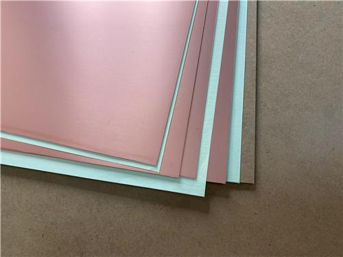
The MEGTRON 6 material family, comprising Laminate R-5775 and Prepreg R-5670, represents Panasonic's advanced high-speed, low-loss printed circuit board material platform. Available in multiple glass cloth variants—Standard E-glass (K/N series) and Low Dk glass (G series)—the product line serves as the industry benchmark for high-frequency and high-speed digital applications requiring low transmission loss, excellent dimensional stability, and superior thermal reliability. These resin systems are engineered with proprietary low-polarity thermosetting polymers that minimize dielectric loss while maintaining the mechanical and thermal properties demanded by high-layer-count PCBs.
2. Material Variants
|
Product Code |
Glass Cloth Type |
Application |
|
R-5775(K) / R-5670(K) |
Standard E-glass |
General high-speed digital |
|
R-5775(N) / R-5670(N) |
Standard E-glass |
High-speed with lead-free assembly |
|
R-5775(G) / R-5670(G) |
Low Dk glass |
Ultra-low loss RF & microwave |
The (G) variant incorporates low dielectric constant glass fibers, resulting in approximately 2-3% lower Dk compared to standard E-glass products, making it particularly advantageous for millimeter-wave applications up to 58GHz and beyond. This design leverages the (G) variant's superior high-frequency performance while benefiting from the mature manufacturing infrastructure established for the MEGTRON family.
|
Part Number |
R-5775(K)/R-5670(K) |
R-5775(N)/R-5670(N) |
R-5775(G)/R-5775(G) |
|
Tg (DSC) |
185 °C |
185 °C |
185 °C |
|
Tg (DMA) |
210 °C |
210 °C |
210°C |
|
Td (Thermal Decomposition) (°C) |
410 °C |
410 °C |
410 °C |
|
T288 (Without Cu) (min) |
>120 min |
>120 min |
>120 min |
|
T288 (With Cu) (min) |
>120 min |
>120 min |
>120 min |
|
CTE-Y |
14-16 ppm/°C |
14-16 ppm/°C |
14-16 ppm/°C |
|
CTE-Y |
14-16 ppm/°C |
14-16 ppm/°C |
14-16 ppm/°C |
|
CTE-Z |
45 ppm/°C |
45 ppm/°C |
45 ppm/°C |
|
CTE α2 Z-axis: Test Method IPC-TM-650 2.4.24; Condition A (ppm/℃) |
260 ppm/°C |
260 ppm/°C |
260 ppm/°C |
|
Thermal Conductivity, (W/m・K) |
0.42 W/m · K |
0.42 W/m · cm |
0.42 W/m · cm |
|
Volume Resistivity (MΩ・cm) |
1 x 10⁹ MΩ · cm |
1 x 10⁹ MΩ · cm |
1 x 10⁹ MΩ · cm |
|
Surface Resistivity (mΩ) |
1 x 10⁸ MΩ |
1 x 10⁸ MΩ |
1 x 10⁸ MΩ |
|
Dielectric Constant (Dk) @ 1Ghz; Test Method IPC-TM-650; Condition C-24/23/50 |
3.4 |
3.4 |
3.4 |
|
Dielectric Constant (Dk) @ 10Ghz; Test Method IPC-TM-650; Condition C-24/23/50 |
—— |
—— |
—— |
|
Dielectric Constant (Dk) @ 12Ghz; Test Method Balanced-type Circular Disk Resonator; Condition C-24/23/50 |
3.4 |
3.4 |
3.4 |
|
Df at 1 GHz |
0.002 |
0.002 |
0.002 |
|
Df at 10 GHz |
—— |
—— |
—— |
|
Df at 12 GHz |
0.004 |
0.004 |
0.004 |
|
Water Absorption (%) |
0.14% |
0.14% |
0.14% |
|
Poisson's Ratio |
0.2 |
0.2 |
0.2 |
|
Flexural Warp (MD) (GPa) |
19 GPa |
19 GPa |
19 GPa |
|
Flexural Fill (TD) (GPa) |
18 GPa |
18 GPa |
18 GPa |
|
Peel Strength (1 Oz. Cu) (kN/m) |
0.8 (Cu:H-VLP) kN/m |
0.8 (Cu:H-VLP) kN/m |
0.8 (Cu:H-VLP) kN/m |
|
Flammability |
94V-0 |
94V-0 |
94V-0 |
3.MEGTRON 6 (G)–Core Material Dielectric Properties
|
Core Type |
Actual Thickness |
Cloth Style |
ply |
Typical Resin Content (%) |
Typical Df |
||||||
|
mil |
mm |
1 GHz |
13 GHz |
24 GHz |
36 GHz |
47 GHz |
58 GHz |
||||
|
2 |
2 |
0.05 |
1035 |
1 |
67 |
0.002 |
0.0037 |
0.004 |
0.0043 |
0.0044 |
0.0046 |
|
2.6 |
2.6 |
0.065 |
1078 |
1 |
59 |
0.002 |
0.0037 |
0.004 |
0.0042 |
0.0044 |
0.0046 |
|
3 |
3 |
0.075 |
1078 |
1 |
65 |
0.002 |
0.0037 |
0.004 |
0.0042 |
0.0044 |
0.0046 |
|
3.5 |
3.5 |
0.09 |
1078 |
1 |
70 |
0.002 |
0.0037 |
0.004 |
0.0043 |
0.0044 |
0.0046 |
|
4 |
3.9 |
0.1 |
2013 |
1 |
56 |
0.002 |
0.0037 |
0.004 |
0.0042 |
0.0044 |
0.0046 |
|
4 |
3.9 |
0.1 |
1035 |
2 |
67 |
0.002 |
0.0037 |
0.004 |
0.0043 |
0.0044 |
0.0046 |
|
5 |
5 |
0.127 |
1078 |
2 |
59 |
0.002 |
0.0037 |
0.004 |
0.0042 |
0.0044 |
0.0046 |
|
5 |
4.9 |
0.125 |
2116 |
1 |
56 |
0.002 |
0.0037 |
0.004 |
0.0042 |
0.0044 |
0.0046 |
|
6 |
5.7 |
0.146 |
1078 |
2 |
65 |
0.002 |
0.0037 |
0.004 |
0.0042 |
0.0044 |
0.0046 |
|
7 |
7 |
0.178 |
1078 |
2 |
70 |
0.002 |
0.0037 |
0.004 |
0.0043 |
0.0044 |
0.0046 |
|
8 |
7.9 |
0.2 |
2013 |
2 |
56 |
0.002 |
0.0037 |
0.004 |
0.0042 |
0.0044 |
0.0046 |
|
10 |
9.8 |
0.25 |
2116 |
2 |
56 |
0.002 |
0.0037 |
0.004 |
0.0042 |
0.0044 |
0.0046 |
|
12 |
11.8 |
0.3 |
2013 |
3 |
56 |
0.002 |
0.0037 |
0.004 |
0.0042 |
0.0044 |
0.0046 |
|
16 |
15.7 |
0.4 |
2013 |
4 |
56 |
0.002 |
0.0037 |
0.004 |
0.0042 |
0.0044 |
0.0046 |
|
20 |
19.7 |
0.5 |
2116 |
4 |
56 |
0.002 |
0.0037 |
0.004 |
0.0042 |
0.0044 |
0.0046 |
|
25 |
24.6 |
0.625 |
2116 |
5 |
56 |
0.002 |
0.0037 |
0.004 |
0.0042 |
0.0044 |
0.0046 |
|
30 |
29.5 |
0.75 |
2116 |
6 |
56 |
0.002 |
0.0037 |
0.004 |
0.0042 |
0.0044 |
0.0046 |
4. MEGTRON 6 (G)–Prepreg R-5670 Properties
|
Cloth Style |
Resin Content (%) |
Typical Thickness |
Typical Dk |
|||||
|
(um) |
1 GHz |
13 GHz |
24 GHz |
36 GHz |
47 GHz |
58 GHz |
||
|
1035 |
72 |
60 |
3.2 |
3.13 |
3.13 |
3.13 |
3.13 |
3.13 |
|
75 |
68 |
3.16 |
3.1 |
3.1 |
3.1 |
3.1 |
3.1 |
|
|
77 |
74 |
3.13 |
3.08 |
3.08 |
3.08 |
3.08 |
3.08 |
|
|
1078 |
66 |
77 |
3.26 |
3.2 |
3.2 |
3.2 |
3.2 |
3.2 |
|
70 |
89 |
3.22 |
3.16 |
3.16 |
3.16 |
3.16 |
3.16 |
|
|
74 |
104 |
3.17 |
3.11 |
3.11 |
3.11 |
3.11 |
3.11 |
|
|
77 |
118 |
3.13 |
3.08 |
3.08 |
3.08 |
3.08 |
3.08 |
|
|
2013 |
56 |
98 |
3.4 |
3.34 |
3.34 |
3.34 |
3.34 |
3.34 |
|
59 |
106 |
3.37 |
3.29 |
3.29 |
3.29 |
3.29 |
3.29 |
|
|
2116 |
56 |
125 |
3.4 |
3.34 |
3.34 |
3.34 |
3.34 |
3.34 |
|
58 |
132 |
3.37 |
3.31 |
3.31 |
3.31 |
3.31 |
3.31 |
|
5. Material Storage and Handling Requirements
6.Processing Guidelines
6.1 Drilling Parameters:
6.2 Lamination Parameters:
6.3 Desmear Process:
6.4 Plating Compatibility:
7.Conclusion
This 14-layer Megtron-6 PCB with ENEPIG surface finish represents a high-performance solution for modern high-speed electronic systems, combining precision manufacturing, industry-leading material technology, and strict quality control. The PCB’s optimized layer stackup, tightly controlled impedance parameters, and robust construction ensure exceptional signal integrity and reliability, while the Megtron-6 material system delivers the ultra-low loss and thermal stability required for high-frequency operation. The ENEPIG surface finish provides excellent solderability and corrosion resistance, supporting long-term reliability in both consumer and industrial applications.
Backed by IPC-3 manufacturing standards and 100% electrical testing, this PCB is designed to meet the most demanding requirements of today’s advanced electronic devices, offering a reliable, high-performance foundation for 5G/6G communication, data center, and aerospace systems. When paired with the advanced properties of the Megtron-6 CCL system, this PCB delivers a level of performance and consistency that sets it apart from standard FR-4 PCBs, making it the ideal choice for applications where signal integrity and reliability are non-negotiable.





Previous:
14-Layer Megtron6 (M6) High-Speed PCB 2.123mm with ENEPIG Surface Finish Impedance ControlNext:
12-layer TG200 TU-872 SLK High-Speed FR4 1.68mm PCB with ENIG Impedance ControlIf you have questions or suggestions,please leave us a message,we will reply you as soon as we can!
Categories
New Products

Wangling F4BTMS220 2-Layer DK2.2 PCB 10 mil Core with Immersion Gold

Wangling F4BTME350 10mil DK3.5 High Frequency Substrate PCB 2-Layer Immersion Gold

Wangling F4BTM300 Custom 2-layer PCB 20mil DK3.0 Substrate with Immersion Gold

Rogers 20mil RT/duroid 6202 2-layer ENIG High-Frequency Microwave PCB

Rogers 20mil AD250C PCB Pure Gold High-Frequency Antenna Circuit Board

8-Layer Hybrid RF PCB: RO4350B + TG170 FR-4 + RO4003C with RO4450F Bondply

4-Layer Rogers RO3010 Hybrid PCB Immersion Silver 2.8mm Finished Thickness

4-Layer 20mil Rogers RO3210 ISIG High-Frequency PCB with Controlled Depth Milling
Base material: RO4350B 0.508 mm + FR4 0.6mm + PP 0.306mm
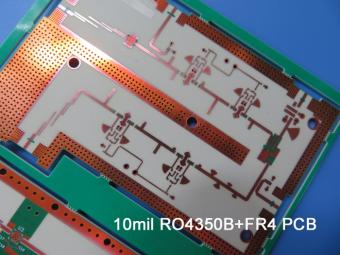
It’s for the application of 2.4 Ghz Antenna. It's 1.0 mm thick with through holes. Green solder mask covers both sides and immersion gold on pads.
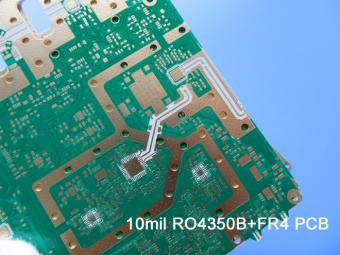
This type is more complex. The 10mil RO4350B core is the same. The main difference is that it contains 3 types blind via.
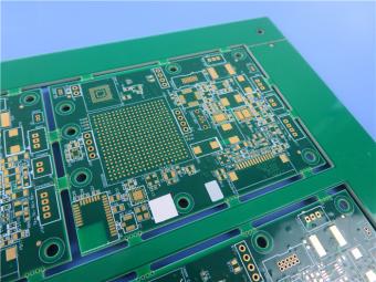
This is a type of 14-layer HDI printed circuit board built on FR-4 Tg170 substrate for the application of codec equipment.
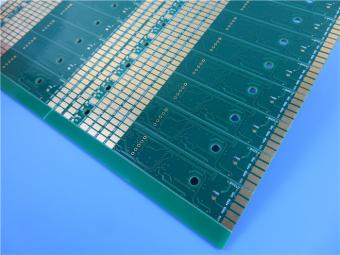
This is a type of High-Tg 4-layer PCB Built on TU-768 material. Each layer is plated with 1oz copper.
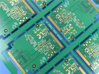
ThunderClad 2 ( TU-883 ) is a very low loss category material based on a high performance resin.
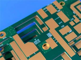
TU-872 SLK copper clad laminate stands out as a high-performance material solution for advancedmultilayer PCBs.
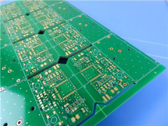
This 12-layer TG200 FR4 PCB is not just a component; it is a carefully engineered platform for high-performance electronics. Its construction combines a sophisticated stackup, advanced via technology, and precision impedance control to create a solution that meets the rigorous demands of modern high-speed digital and telecommunications systems.
 6-11C Shidai Jingyuan, Fuyong, Baoan, Shenzhen, Guangdong, China 518103


For inquiries about our products or pricelist, please leave to us and we will be in touch within 24 hours.
© Copyright: 2026 Shenzhen Bicheng Electronics Technology Co., Ltd.. All Rights Reserved.

IPv6 network supported


