

 Call Us Now !
Tel : +86 755 27374946
Call Us Now !
Tel : +86 755 27374946
 Order Online Now !
Email : info@bichengpcb.com
Order Online Now !
Email : info@bichengpcb.com
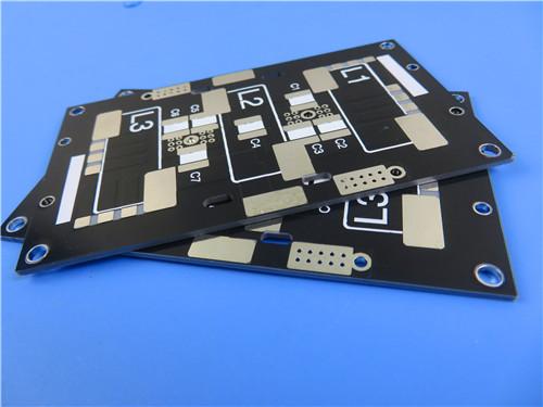
This 20mil F4BTMS450 2-layer PCB with HASL LF finish delivers a reliable, cost-effective high-frequency circuit platform built on an aerospace-grade PTFE ceramic substrate.
Item NO.:
BIC-595-v680.0Order(MOQ):
1-10Payment:
T/TProduct Origin:
ChinaShipping Port:
ShenzhenLead Time:
7-10 days
20mil F4BTMS450 Wangling DK4.5 Laminate Custom PCB HASL LF Finsh
Overview
This product page presents a 2-layer high-frequency printed circuit board built on Wangling F4BTMS450 PTFE ceramic-filled substrate with a 20 mil (0.508 mm) core thickness and Hot Air Solder Leveling lead-free (HASL LF) surface finish. Engineered for RF and microwave applications requiring tight dielectric constant control and low insertion loss, the board features 1 oz finished copper, a 0.6 mm overall thickness, and IPC-Class-2 workmanship standards. The following content is organized into two independent sections: the first covers the PCB itself—construction, stackup, design statistics, and quality assurance—and the second provides an in-depth technical deep dive into the F4BTMS450 copper clad laminate material, including a complete data sheet, performance characteristics, and available configurations.
Part I—PCB Product Description
1. PCB Construction Details
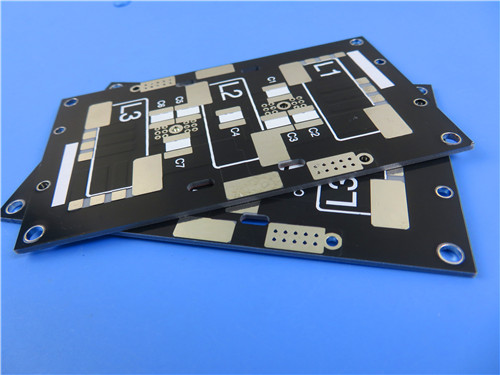
The table below summarizes the core mechanical, electrical, and cosmetic specifications of this 2-layer F4BTMS450 PCB, from base material and copper weight to surface finish and solder mask configuration.
|
Parameter |
Specification |
|
Base Material |
F4BTMS450 (PTFE + ceramic + ultra-fine glass fiber) |
|
Layer Count |
2-layer rigid |
|
Board Dimensions |
38.4 mm × 56.35 mm (±0.15 mm) |
|
Minimum Trace / Space |
4 mil / 6 mil |
|
Minimum Hole Size |
0.3 mm |
|
Blind Vias |
None |
|
Finished Board Thickness |
0.6 mm |
|
Finished Copper Weight |
1 oz (35 μm / 1.4 mil) |
|
Via Plating Thickness |
20 μm |
|
Surface Finish |
HASL LF (Lead-Free Hot Air Solder Leveling) |
|
Top Silkscreen |
White |
|
Bottom Silkscreen |
None |
|
Top Solder Mask |
Black |
|
Bottom Solder Mask |
None |
|
Electrical Test |
100% tested prior to shipment |
|
Quality Standard |
IPC-Class-2 |
|
Artwork Format |
Gerber RS-274-X |
|
Availability |
Worldwide |
2. PCB Stackup
This 2-layer rigid stackup employs a symmetrical structure with 35μm copper foil on both sides of a 0.508 mm (20 mil) F4BTMS450 dielectric core, delivering consistent impedance control across the board.
|
Layer |
Material |
Thickness |
|
Top Copper (Layer 1) |
RTF Copper Foil |
35 μm (1 oz) |
|
Dielectric Core |
F4BTMS450 |
0.508 mm (20 mil) |
|
Bottom Copper (Layer 2) |
RTF Copper Foil |
35 μm (1 oz) |
3. PCB Design Statistics
The following statistics quantify the circuit density and component footprint of this specific board design, reflecting a relatively low-density layout optimized for RF signal integrity rather than component packing.
|
Metric |
Count |
|
Components |
13 |
|
Total Pads |
20 |
|
Through-Hole Pads |
12 |
|
Top SMT Pads |
8 |
|
Bottom SMT Pads |
0 |
|
Vias |
9 |
|
Nets |
5 |
PCB Conclusion
This 20mil F4BTMS450 2-layer PCB with HASL LF finish delivers a reliable, cost-effective high-frequency circuit platform built on an aerospace-grade PTFE ceramic substrate. With a controlled 4.5 Dk, tight tolerance of±0.09, and stable performance across frequency and temperature extremes, it is well-suited for microwave circuits, feed networks, phased array antenna elements, and satellite communication sub-systems. The 0.6 mm finished thickness, 4/6 mil trace/space capability, and IPC-Class-2 quality standard strike a practical balance between RF performance and manufacturability for both prototype evaluation and small-batch production.
Part II—F4BTMS450 Copper Clad Laminate (CCL) Technical Deep Dive
1. Material Overview
The F4BTMS series is an upgraded generation of PTFE-based high-frequency laminates developed by Taizhou Wangling Insulation Materials Factory, building upon the earlier F4BTM platform with breakthroughs in material formulation and manufacturing process. F4BTMS450 is the Dk 4.5 variant within this series, engineered for applications requiring a moderate dielectric constant combined with ultra-low loss and exceptional dimensional stability. Classified as an aerospace-grade high-reliability material, F4BTMS450 is positioned as a domestic alternative to comparable imported PTFE ceramic substrates.
2. Material Composition & Engineering Architecture
At its core, F4BTMS450 combines three key constituents: polytetrafluoroethylene (PTFE) resin as the matrix, a high loading of uniformly dispersed nano-ceramic fillers, and a minimal amount of ultra-thin, ultra-fine glass fiber cloth for mechanical reinforcement.
This formulation strategy is deliberate. Traditional PTFE-glass substrates suffer from the "glass fiber effect"—localized variations in dielectric constant caused by the non-uniform distribution of glass yarns, which degrade signal integrity at microwave frequencies. By minimizing glass fiber content and relying primarily on homogeneously mixed ceramic fillers, F4BTMS450 reduces the glass fiber effect to a minimum. The result is lower and more consistent dielectric loss, reduced X/Y/Z anisotropy, improved dimensional stability, a higher usable frequency range, enhanced electrical strength, and better thermal conductivity compared to glass-fiber-dominant PTFE laminates.
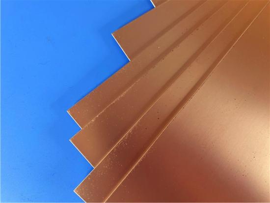
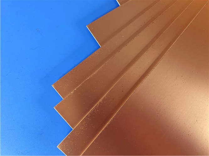
Standard copper foil for F4BTMS450 is Reverse Treated Foil (RTF) with low surface roughness. Low-roughness copper reduces conductor loss at microwave and millimeter-wave frequencies, where skin depth becomes extremely shallow and surface roughness directly contributes to insertion loss. Despite the smooth surface, RTF foil maintains excellent peel strength exceeding 1.2 N/mm for 1 oz copper, ensuring robust copper-to-dielectric adhesion through thermal cycling and assembly processes.
3. Complete Electrical & Mechanical Data Sheet
The table below presents the full technical specification set for F4BTMS450, tested per IPC-TM-650 and relevant GB standards.
|
Property |
Test Condition |
Unit |
F4BTMS450 Value |
|
Dielectric Constant (typical) |
10 GHz |
— |
4.5 |
|
Dielectric Constant Tolerance |
— |
— |
±0.09 |
|
Dielectric Constant (design value) |
10 GHz |
— |
4.5 |
|
Dissipation Factor (typical) |
2 GHz |
— |
0.0015 |
|
Dissipation Factor (typical) |
10 GHz |
— |
0.0019 |
|
Dissipation Factor (typical) |
20 GHz |
— |
0.0024 |
|
Thermal Coefficient of Dk (TCDk) |
-55°C ~ 150°C |
ppm/°C |
-58 |
|
Peel Strength |
1 oz RTF copper |
N/mm |
>1.2 |
|
Volume Resistivity |
Normal condition |
MΩ·cm |
≥1×10⁸ |
|
Surface Resistance |
Normal condition |
MΩ |
≥1×10⁸ |
|
Electrical Strength (Z-direction) |
5 kW, 500 V/s |
kV/mm |
>45 |
|
Breakdown Voltage (XY-direction) |
5 kW, 500 V/s |
kV |
>54 |
|
CTE (X, Y direction) |
-55°C ~ 288°C |
ppm/°C |
12, 12 |
|
CTE (Z direction) |
-55°C ~ 288°C |
ppm/°C |
45 |
|
Thermal Stress |
260°C, 10 s, 3 cycles |
— |
No delamination |
|
Moisture Absorption |
20±2°C, 24 hours |
% |
0.08 |
|
Density |
Room temperature |
g/cm³ |
2.53 |
|
Continuous Operating Temperature |
Thermal chamber |
°C |
-55 ~ +260 |
|
Thermal Conductivity |
Z-direction |
W/(m·K) |
0.64 |
|
Flame Retardancy |
— |
UL-94 |
V-0 |
|
Material Composition |
— |
— |
PTFE, ultra-fine glass fiber, ceramic |
Note: Dielectric constant is measured in the Z-direction per GB/T 12636-1990 or IPC-TM-650 2.5.5.5 stripline method. All other properties are tested per or referenced to IPC-TM-650 or GB/T 4722-2017. Values are typical measurements for material selection reference.
4. Key Performance Differentiators
1) Tight Dk Tolerance of±0.09.
Unlike general-purpose FR-4 materials with Dk tolerances commonly in the±10% range, F4BTMS450 holds Dk to±0.09 around the 4.50 nominal—a variation of only±2%. This batch-to-batch consistency is critical for phase-sensitive applications such as phased array antennas, where element-to-element phase matching directly determines beam steering accuracy and side-lobe performance.
2) Ultra-Low Dissipation Factor.
With a Df of just 0.0019 at 10 GHz and 0.0024 at 20 GHz, F4BTMS450 delivers significantly lower insertion loss than epoxy-based high-frequency materials. For a 50-ohm transmission line at 10 GHz, this translates to measurable improvements in power efficiency, signal-to-noise ratio, and effective range in radar and communication systems.
3) Exceptional Thermal Coefficient of Dk (TCDk).
At -58 ppm/°C across -55°C to 150°C, F4BTMS450 exhibits one of the lowest TCDk values among PTFE-ceramic substrates. This means resonant frequency drift of filters and antennas remains minimal across wide temperature swings—essential for outdoor, aerospace, and defense deployments.
4) Balanced CTE Profile.
The X/Y CTE of 12 ppm/°C closely matches that of copper (approximately 17 ppm/°C), reducing shear stress at the copper-dielectric interface during thermal cycling. The Z-axis CTE of 45 ppm/°C is notably low for a PTFE-based material, enhancing plated-through-hole reliability—validated by the 260°C, 10-second, 3-cycle thermal stress test with no delamination.
5) Elevated Thermal Conductivity.
At 0.64 W/(m·K), F4BTMS450 offers roughly 1.5 to 2 times the thermal conductivity of standard FR-4 (typically 0.3–0.4 W/(m·K)), improving heat dissipation for power amplifier circuits and active antenna arrays without the added cost of metal-core substrates.
6) Low Moisture Absorption of 0.08%.
PTFE's inherently hydrophobic nature, combined with dense ceramic loading, keeps moisture absorption at a minimal 0.08% after 24-hour immersion. This ensures stable electrical performance in high-humidity environments and prevents the Dk shift and dimensional swelling that plague hydrocarbon and some thermoset high-frequency materials.
5. Frequency & Temperature Stability
Measured data across the 0.5 to 20 GHz range confirms that F4BTMS450 maintains a flat dielectric constant response, with Dk remaining close to the 4.50 nominal and dissipation factor increasing only gradually from 0.0015 at 2 GHz to 0.0024 at 20 GHz. This stability supports designs intended for multi-band operation without the need for frequency-specific Dk de-rating.
On the temperature axis, from -55°C to 150°C, the Dk follows a near-linear downward trend governed by the -58 ppm/°C TCDk, while dissipation factor remains well-controlled. The actual usable temperature range extends beyond the characterized window, rated for continuous operation from -55°C to +260°C—a range few organic substrate families can match without degradation.
6. Recommended Applications
7. Available Configurations
7.1 Copper Foil Options.
Standard configurations include 0.5 oz (18μm) and 1 oz (35μm) RTF low-roughness copper foil; other thicknesses are available upon custom request. For applications requiring integrated resistive elements, F4BTMS450 can be supplied with embedded 50Ωresistor foil—a nickel-phosphorus alloy resistive layer of 0.2μm thickness with a sheet resistance of 50±5Ωper square.
7.2 Panel Sizes.
Standard production panel dimensions include:
Custom sizes can be arranged through direct consultation.
7.3 Available Core Thicknesses (F4BTMS450):
Minimum 0.254mm (10 mil). Standard thicknesses include:
8. Metal Base Variants
For applications requiring enhanced thermal management or electromagnetic shielding, F4BTMS450 is also available in metal-backed configurations:
Both variants consist of dielectric on one side with copper foil circuitry, and metal base on the opposite side—serving dual functions of heat dissipation and electromagnetic shielding for ground plane or cavity-backed antenna designs.
CCL Conclusion
F4BTMS450 represents a mature, well-characterized PTFE-ceramic high-frequency laminate that combines aerospace-grade reliability with practical manufacturability. Its key strengths—a tightly controlled Dk of 4.50±0.09, ultra-low dissipation factor across 2–20 GHz, a TCDk of only -58 ppm/°C, balanced 12/45 ppm/°C CTE values, 0.64 W/(m·K) thermal conductivity, and UL-94 V-0 flame rating—make it a compelling choice for microwave circuits, phased array antennas, radar systems, satellite communications, and aerospace electronics. With standard RTF copper foil, a broad range of thickness options from 10 to 250 mil, and optional copper or aluminum metal bases, F4BTMS450 provides design engineers with a versatile high-frequency substrate platform that can be tailored to diverse performance and thermal requirements.





Previous:
Wangling F4BM245 PCB 20mil Laminate 2-Layer Immersion Gold No Solder Mask SilkscreenNext:
Wangling WL-CT300 5mil Laminate Pure Gold Plating High Frequency PCBIf you have questions or suggestions,please leave us a message,we will reply you as soon as we can!
Categories
New Products
Wangling TP2200 PCB 0.8mm Substrate Immersion Gold 2-Layer High-Dk (Dk 22) RF Board
Rogers TMM10 PCB 5.08mm Core ENIG 2-Layer High-Dk Microwave Board
Taconic TLX-8 PCB 50mil ENIG 2-Layer High-Frequency RF Circuit Board
Wangling TF440 25mil DK4.4 Laminate Immersion Gold 2-Layer Copper-filling Vias PCB
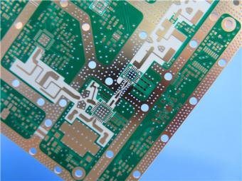
RO4360G2 Rogers 12mil ENEPIG 2-Layer DK6.15 High Frequency Custom PCB

Wangling F4BTMS220 2-Layer DK2.2 PCB 10 mil Core with Immersion Gold

Wangling F4BTME350 10mil DK3.5 High Frequency Substrate PCB 2-Layer Immersion Gold

Wangling F4BTM300 Custom 2-layer PCB 20mil DK3.0 Substrate with Immersion Gold
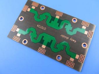
Polytetrafluoroethylene (Short for PTFE), commonly known as "plastic king ", is a polymer compound made of tetrafluoroethylene by polymerization. It has excellent chemical stability, corrosion resistance, sealing, high lubrication and non-viscosity, electrical insulation and good aging resistance.
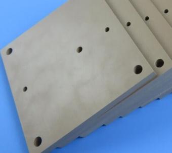
Rogers TMM4 thermoset microwave material is ceramic, hydrocarbon, thermoset polymer composite designed for high plated-through-hole reliability stripline and microstrip applications.
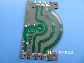
Taconic TLY laminates are a type of low loss laminates. They are manufactured with very light weight woven fiberglass and are more dimensionally stable than chopped fiber reinforced PTFE composites.
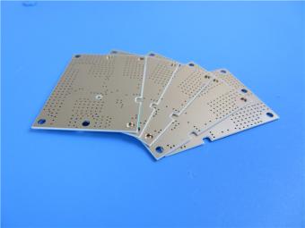
RO3203 laminates combine the surface smoothness of a non-woven PTFE laminate, for finer line etching tolerances, with the rigidity of a woven-glass PTFE laminate. These materials can be fabricated into printed circuit boards using
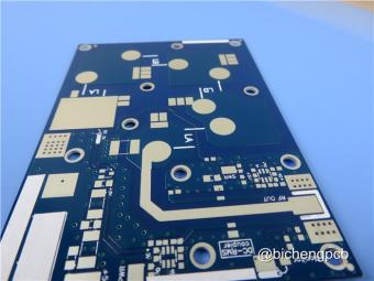
This type of immersion silver RF PCB is made on one of Taconic’s ORCER family material: RF-45.
Rogers’ TMM10 thermoset microwave materials are ceramic, hydrocarbon, thermoset polymer composites designed for high plated-thru-hole reliability stripline and microstrip applications.
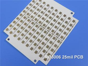
Rogers RO3006 was designed to offer exceptional electrical and mechanical stability at competitive prices.
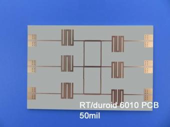
RT/duroid 6010LM microwave laminates feature ease of fabrication and stability in use. This property results in the possibility of mass production and reducing the cost of goods.
 6-11C Shidai Jingyuan, Fuyong, Baoan, Shenzhen, Guangdong, China 518103


For inquiries about our products or pricelist, please leave to us and we will be in touch within 24 hours.
© Copyright: 2026 Shenzhen Bicheng Electronics Technology Co., Ltd.. All Rights Reserved.

IPv6 network supported


