

 Call Us Now !
Tel : +86 755 27374946
Call Us Now !
Tel : +86 755 27374946
 Order Online Now !
Email : info@bichengpcb.com
Order Online Now !
Email : info@bichengpcb.com
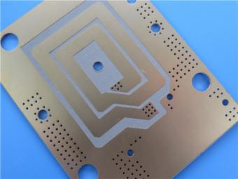
This 32mil TRF-45 Immersion Gold PCB integrates Taconic's industry-leading high-frequency laminate technology with precision PCB manufacturing to deliver a reliable, high-performance solution for demanding RF and microwave applications.
Item NO.:
BIC-547-v632.0Order(MOQ):
1-10Payment:
T/TProduct Origin:
ChinaShipping Port:
ShenzhenLead Time:
7-10 days
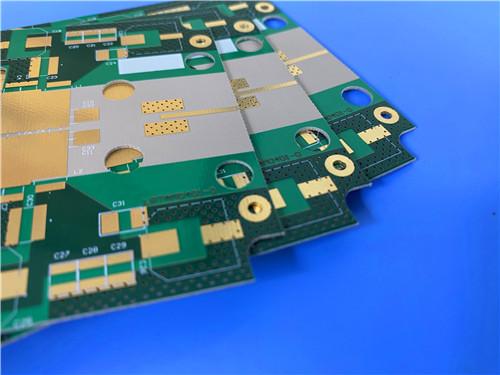
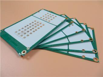
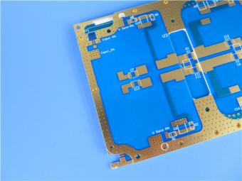
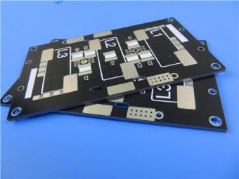
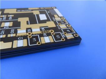
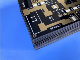
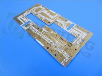
32mil TRF-45 Taconic Substrate Double-sided PCB Immersion Gold Green Solder Mask
PCB Product Overview
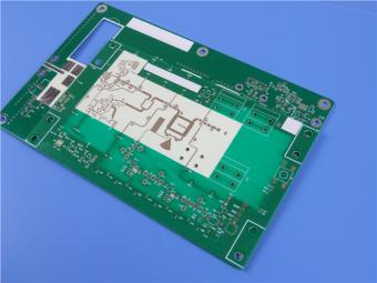
This is high-performance 32mil TRF-45 double-sided rigid PCB with immersion gold surface finish, engineered specifically for mission-critical radio-frequency, microwave, and high-speed digital applications. Built on Taconic's advanced TRF-45 ceramic-filled PTFE laminate, this board delivers exceptional low-loss performance, stable dielectric properties, outstanding thermal stability, and excellent dimensional control across extreme operating conditions. It is fully manufactured to IPC-Class-2 quality standards, supported by 100% electrical testing before shipment, making it a trusted solution for satellite communications, RFID systems, GPS antennas, and other high-reliability RF modules. The immersion gold surface finish ensures superior solderability, contact conductivity, corrosion resistance, and long-term durability in challenging environments. This Taconic high frequency PCB combines material excellence, precision fabrication, and strict quality assurance to satisfy the most demanding performance and reliability requirements of modern electronic systems.

1. PCB Construction
This section summarizes the core mechanical, electrical, and surface characteristics of the finished PCB, defining its build specifications, tolerances, and processing features.
|
Parameter |
Specification |
|
Base Material |
TRF 45 |
|
Layer Count |
Double sided (2 layer rigid) |
|
Board Dimensions |
105mm × 76mm per piece, tolerance ±0.15mm |
|
Minimum Trace / Space |
4/6 mils |
|
Minimum Hole Size |
0.25mm |
|
Blind Vias |
None |
|
Finished Board Thickness |
0.9mm |
|
Finished Copper Weight |
1oz (1.4 mils) on outer layers |
|
Via Plating Thickness |
20μm |
|
Surface Finish |
Immersion Gold (ENIG) |
|
Top Silkscreen |
White |
|
Bottom Silkscreen |
None |
|
Top Solder Mask |
Green |
|
Bottom Solder Mask |
None |
|
Pre Shipment Quality |
100% full electrical test |
2. PCB Stackup
The stackup defines the layer structure and thickness distribution, balancing mechanical rigidity, signal integrity, and thermal performance.
|
Layer |
Material & Thickness |
|
Copper Layer 1 |
35μm (1oz electrodeposited copper) |
|
Dielectric Core |
TRF 45, 0.813mm (32mil) |
|
Copper Layer 2 |
35μm (1oz electrodeposited copper) |
3. PCB Layout Statistics
This table provides key design and assembly statistics, supporting component mounting, routing efficiency, and production verification.
|
Item |
Quantity |
|
Components |
42 |
|
Total Pads |
38 |
|
Through Hole Pads |
25 |
|
Top SMT Pads |
13 |
|
Bottom SMT Pads |
0 |
|
Vias |
15 |
|
Nets |
2 |
4. Design, Quality, and Supply Conditions
TRF-45 Laminate Material Knowledge Base
This section provides a detailed technical introduction to Taconic TRF-45 laminate, the core dielectric used in the above 32mil TRF-45 PCB. It includes material properties, typical values, copper foil options, thickness availability, and application guidance.
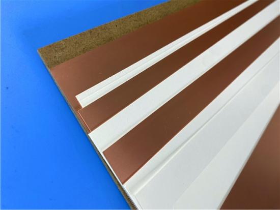
1. Basic Introduction to TRF-45 CCL
TRF-45 is a next-generation high-performance copper clad laminate developed by Taconic Advanced Dielectric Division, designed specifically for low-loss, thermally stable RF and microwave applications. It is a woven-glass reinforced, ceramic-filled PTFE composite that integrates advanced ceramic filling technology with robust fiberglass reinforcement to achieve an optimal balance of electrical performance, mechanical strength, thermal stability, and manufacturability. Unlike standard PTFE materials, Taconic TRF-45 offers greatly improved dimensional stability and controlled Z-axis expansion, making it highly reliable under soldering and extreme thermal cycling conditions. It supports conventional PCB fabrication processes including shearing, drilling, plating, and etching, enabling broad adoption in professional RF manufacturing.

2. Core Performance Parameters of TRF-45 CCL
|
Property |
Test Method |
Unit |
TRF-45 Typical Value |
|
Dielectric Constant (Dk) @10GHz |
IPC-TM-650 2.5.5.6 |
– |
4.5±0.15 |
|
Dissipation Factor (Df) @10GHz |
IPC-TM-650 2.5.5.5.1(m) |
– |
0.0035 |
|
Moisture Absorption |
IPC-TM-650 2.6.2.1 |
% |
0.06 |
|
Surface Resistivity |
IPC-TM-650 2.5.17.1 |
MΩ |
3.0×10⁷ |
|
Volume Resistivity |
IPC-TM-650 2.5.17.1 |
MΩ·cm |
8.0×10⁷ |
|
Flexural Strength (Lengthwise) |
IPC-TM-650 2.4.4 |
N/mm² |
177 |
|
Flexural Strength (Crosswise) |
IPC-TM-650 2.4.4 |
N/mm² |
103 |
|
Peel Strength |
IPC-TM-650 2.4.8 |
N/mm |
1.4 |
|
Thermal Conductivity |
ASTM F433 |
W/m·K |
0.43 |
|
CTE (X axis, 50–150°C) |
ASTM D3386 (TMA) |
ppm/°C |
9 |
|
CTE (Y axis, 50–150°C) |
ASTM D3386 (TMA) |
ppm/°C |
9 |
|
CTE (Z axis, 50–150°C) |
ASTM D3386 (TMA) |
ppm/°C |
40 |
|
Flammability |
UL 94 |
– |
V-0 |
3. Key Material Advantages
1)Ultra-low loss: Df = 0.0035 @10GHz supports long-distance, high-frequency signal transmission with minimal attenuation.
2)Stable dielectric properties: Dk remains tightly controlled across temperature and frequency, ensuring consistent impedance and circuit performance.
3)Excellent thermal stability: Low and consistent Z-axis expansion reduces stress on vias and conductors during thermal shock.
4)High dimensional stability: Woven glass reinforcement minimizes warpage and twist, supporting fine-line and high-precision fabrication.
5)Low moisture absorption: Only 0.06% moisture uptake preserves electrical stability in high-humidity environments.
6)Good thermal conductivity: Efficient heat dissipation improves reliability for power RF circuits.
7)UL 94 V-0 flammability: Meets strict safety requirements for industrial, automotive, and aerospace use.
8)Compatibility with standard processes: Supports drilling, plating, and etching using standard PTFE PCB manufacturing methods.
4.Typical Thicknesses Available
TRF-45 substrate is supplied in various dielectric thicknesses, with standard tolerances according to IPC-4103/Class B for thicknesses≥64mils.
|
Inch |
mm |
|
0.008 |
0.2 |
|
0.016 |
0.41 |
|
0.024 |
0.61 |
|
0.032 |
0.81 |
|
0.04 |
1.02 |
|
0.064 |
1.63 |
|
0.12 |
3.05 |
5.Copper Foil Options
TRF-45 is cladded with electrodeposited (ED) copper foils having different profiles. The choice of foil affects insertion loss and peel strength.
|
Designation |
Copper Weight |
Thickness |
Treatment Type |
|
CLH |
½ oz |
~18μm |
Reverse treated ED |
|
CL1 |
1 oz |
~35μm |
Reverse treated ED |
|
CVH (CH) |
½ oz |
~18μm |
Very low profile ED |
|
CV1 (C1) |
1 oz |
~35μm |
Very low profile ED |
|
C2 |
2 oz |
~70μm |
Electrodeposited |
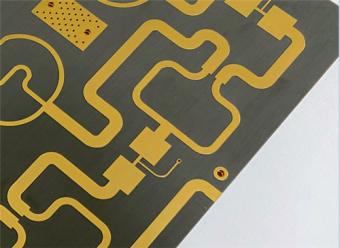
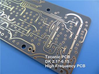
6. Typical Applications of TRF-45 CCL
TRF-45 CCL is widely used in high-performance RF and microwave components:
7.Processing Guidelines
1)TRF-45 can be drilled, routed, and plated using conventional methods for woven-glass PTFE materials. Key considerations:
2)Use carbide drills with high chip-load to avoid smearing.
3)Plasma or chemical etch treatment is recommended before electroless copper deposition to improve adhesion.
4)Solder mask adhesion may require a sodium naphthalate or plasma etch pre-treatment.
5)Reflow soldering is compatible with the material's low Z-axis CTE (40ppm/°C), reducing via barrel cracking risk.
Conclusion
This 32mil TRF-45 Immersion Gold PCB integrates Taconic's industry-leading high-frequency laminate technology with precision PCB manufacturing to deliver a reliable, high-performance solution for demanding RF and microwave applications. With strict adherence to IPC-Class-2, full electrical testing, stable material properties, and optimized structural design, this board ensures consistent signal integrity, thermal stability, and long-term durability. The accompanying detailed TRF-45 CCL knowledge base provides engineers with full transparency of material behavior, processing compatibility, and performance limits to support accurate design, simulation, and qualification.
For further information or to request a quotation, please contact our technical sales team.


Previous:
2-Layer RF-10 AGC Taconic High Frequency PCB 10mil ENEPIG DK10.2 LaminateNext:
High Frequency PCB Built on Taconic RF-35TC DK3.5 With 60mil Thick and Immersion GoldIf you have questions or suggestions,please leave us a message,we will reply you as soon as we can!
Categories
New Products
Wangling 5mil 0.127mm TFA300 Core 2-layer Immersion Gold Green Solder Mask PCB
7.5mil AGC Taconic TLY-5 Substrate Custom PCB EPIG Finish Bare Copper
10mil Rogers CuClad 250 Immersion Gold 2-Layer Rigid Microwave PCB
20mil F4BTMS450 Wangling DK4.5 Laminate Custom PCB HASL LF Finsh
F4BME275 Wangling DK2.75 Laminate 2-Layer 1.6mm Pure Gold RF Custom PCB
Wangling F4BTD350S High Frequency PCB 2-layer 20mil Thick ENIG DK3.5 Substrate

12-layer TG200 TU-872 SLK High-Speed FR4 1.68mm PCB with ENIG Impedance Control

12-Layer RO4350B + RO3010 3.14mm Hybrid PCB Nickel-Free EPIG Surface Finish Blind Via
RF-35TC is a type of high frequency material from Taconic company. It offers a "best in class" low dissipation factor with high thermal conductivity.
TLX offers reliability in a wide range of RF applications. This material is versatile due to its 2.45 - 2.65 DK range and available thicknesses and copper cladding. It is suitable for low layer count microwave designs.

TLF-35A is another type of low cost RF material. It's the best choice for low cost, high volume commercial microwave and radio frequency applications.
CER-10 is an organic-ceramic DK-10 laminate in the ORCER family of Taconic products. It is based on a woven glass reinforcement. CER-10 exhibits exceptional interlaminar bond strength and solder resistance.
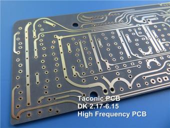
RO4360G2 laminates of Rogers Corporation are 6.15 Dk, low loss, glass-reinforced, hydrocarbon ceramic-filled thermoset materials that provide the ideal balance of performance and processing ease.
RF-60A is an organic-ceramic laminate in the ORganic CERamic(ORCER) family of Taconic products.
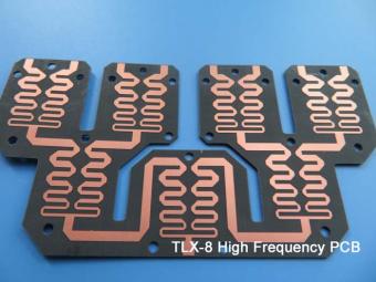
TLX is PTFE based fiberglass laminate, it is ideal for use in radar systems, mobile communications, microwave test equipment, microwave transmission devices and RF components.
TLX offers reliability in a wide range of RF applications. This material is versatile due to its 2.45 - 2.65 DK range and available thicknesses and copper cladding. It is suitable for low layer count microwave designs
 6-11C Shidai Jingyuan, Fuyong, Baoan, Shenzhen, Guangdong, China 518103


For inquiries about our products or pricelist, please leave to us and we will be in touch within 24 hours.
© Copyright: 2026 Shenzhen Bicheng Electronics Technology Co., Ltd.. All Rights Reserved.

IPv6 network supported


