

 Call Us Now !
Tel : +86 755 27374946
Call Us Now !
Tel : +86 755 27374946
 Order Online Now !
Email : info@bichengpcb.com
Order Online Now !
Email : info@bichengpcb.com
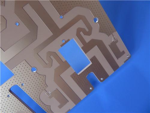
This 4-layer hybrid RO3010 PCB represents a carefully optimized solution for high-frequency RF and microwave applications.
Item NO.:
BIC-623-v708Order(MOQ):
1-10Payment:
T/TProduct Origin:
ChinaShipping Port:
ShenzhenLead Time:
7-10 days
4-Layer Rogers RO3010 Hybrid PCB Immersion Silver 2.8mm Finished Thickness
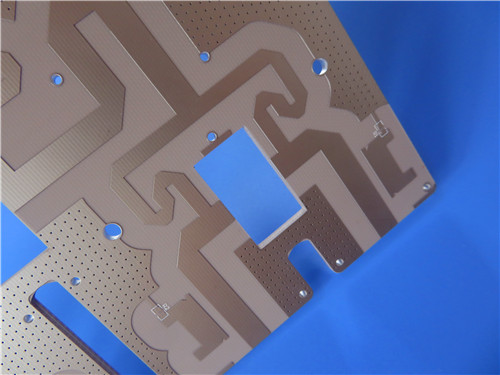
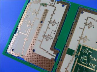
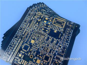
Figure 1. 4-Layer RO3010 High-Frequency PCB with Immersion Silver Finish
Part 1: PCB Product Description
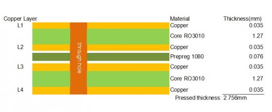
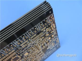
This 4-layer high-frequency board is engineered on a hybrid Rogers RO3010 PCB and FR-4 construction, delivering premium RF performance with practical multi-layer manufacturability. The board pairs two1.27 mm RO3010 dielectric layers — one on the top and one on the bottom — with a single sheet of 1080-style FR-4 prepreg (0.076 mm) as the central bonding layer, resulting in a finished board thickness of 2.8 mm. Each of the four copper layers is finished to 1 oz (35 μm), providing robust current-carrying capacity and consistent impedance control. The outer layers receive an immersion silver surface finish, which offers a flat, solderable, and low-contact-resistance termination ideal for high-frequency circuits.
With no solder mask applied on either side and white silkscreen legend retained, the board is optimized for applications where exposed copper and minimal dielectric overlay are critical to signal integrity. The single-piece panel measures 143 mm × 97.5 mm.
The following table summarizes the complete construction specification of this 4-Layer RO3010 High-Frequency PCB, covering material selection, layer count, dimensional parameters, copper weight, surface finish, and finishing options.
|
Parameter |
Specification |
|
Base Material |
Rogers RO3010 (outer layers) + 1080 FR-4 Prepreg (core) |
|
Layer Count |
4 layers |
|
Board Dimensions |
143 mm × 97.5 mm = 1 PCS |
|
Finished Board Thickness |
2.8 mm |
|
Finished Copper Weight |
1 oz (35 μm) on all 4 layers |
|
Surface Finish |
Immersion Silver (ImAg) |
|
Top Silkscreen |
Yes (White) |
|
Bottom Silkscreen |
Yes (White) |
|
Top Solder Mask |
No |
|
Bottom Solder Mask |
No |
|
Via Type |
Plated Through-Hole (PTH) |
|
Electrical Test |
100% Electrical Test Prior to Shipment |
The stackup below details each layer from top to bottom, specifying the material, copper weight, and dielectric thickness. The symmetric arrangement — RO3010 on both outer sides with an FR-4 prepreg core — ensures balanced mechanical stress and minimal warpage.
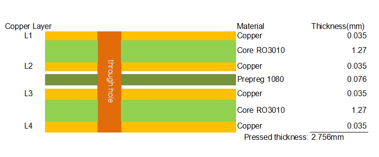
Figure 2. Stackup Diagram: 4-Layer RO3010 Hybrid PCB
The defining characteristic of this PCB is its use ofRogers RO3010as the primary dielectric on both outer signal layers. RO3010 is a ceramic-filled PTFE composite with a process dielectric constant (Dk) of 10.2 ± 0.30 at 10 GHz — among the highest in theRogers RO3000 family. A high Dk material shortens the guided wavelength, allowing designers to shrink the physical dimensions of microstrip antennas, filters, and impedance-matching networks. For a 10 GHz signal, the wavelength in RO3010 is roughly one-third of what it would be in free space, translating directly into more compact circuit layouts — valuable in automotive radar and phased-array designs.
Equally important is the dissipation factor (Df) of 0.0022 at 10 GHz. While not as ultra-low as RO3003 (0.0010), this Df keeps insertion loss manageable well into the millimeter-wave range. In practical terms, a 50-ohm microstrip transmission line on RO3010 exhibits significantly lower conductor and dielectric loss than an equivalent line on standard FR-4, whose Df can exceed 0.02 at the same frequency — nearly an order of magnitude higher. For power amplifier output stages and receiver front-ends, every 0.1 dB of loss reduction directly improves system efficiency and noise figure. The thermal coefficient of Dk (TCDk) of −395 ppm/°C across −50 °C to +150 °C ensures that impedance and filter center frequencies remain stable over wide operating temperature ranges.
The hybrid construction — RO3010 on the outside, FR-4 prepreg in the middle — is a deliberate engineering choice. Pure RO3010 multi-layer boards are expensive because every dielectric layer must be high-frequency laminate. By using a single thin FR-4 prepreg (1080 style, 0.076 mm) as the core bonding layer, the design retains RO3010 on the critical outer signal layers while reducing overall material cost. The1080 prepreg is thin enough that its effect on high-frequency signals routed on the outer layers is negligible, yet it provides reliable interlayer adhesion and mechanical support. This hybrid approach is a well-proven strategy in the RF PCB industry, particularly for 4-layer designs where only the top and bottom layers carry critical RF signals.
Thermo-mechanical stability is another strong point. RO3010 has a coefficient of thermal expansion (CTE) of 13 ppm/°C in the X-axis, 11 ppm/°C in the Y-axis, and 16 ppm/°C in the Z-axis — values closely matched to copper's CTE of approximately 17 ppm/°C. This close match minimizes differential expansion between the dielectric and copper traces during thermal cycling, reducing the risk of trace cracking, via fatigue, and solder joint failure. The Z-axis CTE of 16 ppm/°C is notably low compared to FR-4 (typically 50–70 ppm/°C above Tg), which means plated through-holes experience far less stress during reflow and temperature cycling. For a 2.8 mm thick board with through-hole vias, this Z-axis stability is a significant reliability advantage. The decomposition temperature (Td) of 500 °C further underscores the material's ability to withstand multiple lead-free reflow cycles without degradation.
The immersion silver (ImAg) surface finish is well suited to this product. Unlike ENIG (electroless nickel immersion gold), immersion silver deposits directly onto copper without a nickel barrier layer. At microwave and millimeter-wave frequencies, the nickel layer in ENIG can introduce additional signal loss due to its lower conductivity and ferromagnetic properties. Immersion silver avoids this issue, providing a pure, high-conductivity termination that preserves the RF performance of the underlying copper. Silver also offers excellent solderability and a flat surface ideal for fine-pitch surface-mount components. The trade-off is that silver is susceptible to tarnish under humid conditions, so proper storage in dry packaging and prompt assembly are recommended.
This PCB is targeted at a range of high-frequency applications where performance, size, and reliability must be balanced. Primary applications include 77 GHz automotive radar front-end boards, where the high Dk RO3010 laminate enables compact antenna arrays and the low CTE ensures reliability under the hood. Other suitable uses include satellite communication receiver cards, GPS/GNSS antenna feed networks, RF power amplifier modules for cellular base stations, microwave filters and multiplexers, and point-to-point microwave backhaul radios.
The board's 2.8 mm thickness and 4-layer construction also make it suitable for applications requiring rigid mechanical support alongside RF performance, such as industrial sensor heads and aerospace telemetry modules.
This 4-layer hybrid RO3010 PCB represents a carefully optimized solution for high-frequency RF and microwave applications.
By combining the exceptional electrical properties of Rogers RO3010 — high Dk for miniaturization, low Df for signal fidelity, and CTE matched to copper for reliability — with a cost-effective FR-4 prepreg core, the board delivers premium performance without unnecessary material expense.
The immersion silver finish, solder-mask-free construction, and 1 oz copper further refine the design for high-frequency operation. Whether deployed in automotive radar, satellite communications, or industrial RF systems, this board provides a robust and well-characterized platform for demanding microwave circuits.
Part 2: CCL Material Knowledge — Rogers RO3010
Rogers 3010 is a ceramic-filled polytetrafluoroethylene (PTFE) composite laminate designed specifically for commercial microwave and RF applications. It is the highest-dielectric-constant member of theRogers RO3000 series, which also includes RO3003 (Dk 3.00), RO3006 (Dk 6.15), and RO3035 (Dk 3.50). The RO3000 family was engineered to provide exceptional electrical and mechanical stability at competitive prices, with consistent mechanical properties across all dielectric constant variants. This consistency allows designers to develop multilayer boards using different Dk materials for individual layers without encountering warpage or reliability problems.
RO3010 achieves its high Dk of 10.2 through a high loading of ceramic filler within the PTFE matrix. Unlike glass-reinforced laminates such as the RO4000 series, RO3010 contains no woven glass fabric, resulting in a uniformly homogeneous dielectric that is free of glass-weave effects. This uniformity is particularly beneficial at millimeter-wave frequencies where weave-induced impedance variations can degrade circuit performance.
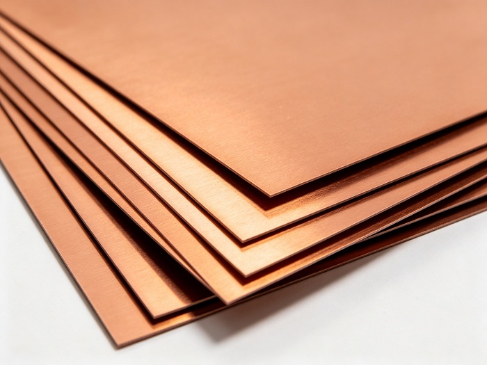
Figure 3. Rogers RO3010 Copper-Clad Laminate (CCL) — Ceramic-Filled PTFE Composite
RO3010 is composed of a PTFE polymer matrix reinforced with ceramic particulate filler. The PTFE matrix provides inherently low dielectric loss and excellent chemical resistance, while the ceramic filler raises the dielectric constant and improves mechanical stiffness and thermal conductivity. The material is supplied as copper-clad laminate (CCL) with electrodeposited (ED) copper foil bonded to one or both sides. Standard copper cladding options include ½ oz (18 μm) and 1 oz (35 μm). The absence of glass reinforcement means that the dielectric is isotropic in the X-Y plane, with no weave-induced Dk variation. This makes RO3010 particularly suitable for tightly coupled circuits such as edge-coupled filters and patch antenna arrays where consistent impedance across the panel is critical.
The following table presents the complete standard properties of RO3010 as specified in the official Rogers datasheet, including electrical, thermal, mechanical, and physical characteristics with their respective test conditions and test methods.
|
Property |
RO3010 Value |
Units |
Test Conditions |
Test Method |
|
Dielectric Constant (process) |
10.2 ± 0.30 |
— |
23 °C, 10 GHz |
IPC TM-650 2.5.5.5 |
|
Dielectric Constant (design) |
11.20 |
— |
8 – 40 GHz |
Differential Phase Length |
|
Dissipation Factor (tan δ) |
0.0022 |
— |
23 °C, 10 GHz |
IPC TM-650 2.5.5.5 |
|
Thermal Coefficient of Dk |
−395 |
ppm/°C |
−50 to 150 °C, 10 GHz |
IPC TM-650 2.5.5.5 |
|
Volume Resistivity |
1×10⁵ |
MΩ·cm |
Condition A |
IPC TM-650 2.5.17.1 |
|
Surface Resistivity |
1×10⁵ |
MΩ |
Condition A |
IPC TM-650 2.5.17.1 |
|
Decomposition Temperature (Td) |
500 |
°C (TGA) |
— |
ASTM D3850 |
|
CTE — X axis |
13 |
ppm/°C |
−55 to 288 °C, 23 °C/50% RH |
IPC TM-650 2.4.41 |
|
CTE — Y axis |
11 |
ppm/°C |
−55 to 288 °C, 23 °C/50% RH |
IPC TM-650 2.4.41 |
|
CTE — Z axis |
16 |
ppm/°C |
−55 to 288 °C, 23 °C/50% RH |
IPC TM-650 2.4.41 |
|
Thermal Conductivity |
0.95 |
W/(m·K) |
50 °C |
ASTM D5470 |
|
Specific Heat Capacity |
0.8 |
J/(g·K) |
— |
Calculated |
|
Copper Peel Strength |
9.4 |
lbs/in |
1 oz ED Cu, After Solder Float |
IPC TM-650 2.4.8 |
|
Young's Modulus (MD / CMD) |
1902 / 1934 |
MPa |
23 °C |
ASTM D638 |
|
Dimensional Stability (MD / CMD) |
−0.35 / −0.31 |
mm/m |
Condition A |
IPC TM-650 2.2.4 |
|
Density |
2.8 |
g/cm³ |
23 °C |
ASTM D792 |
|
Moisture Absorption |
0.05 |
% |
D48/50 |
IPC TM-650 2.6.2.1 |
|
Flammability Rating |
V-0 |
— |
— |
UL 94 |
|
Lead-Free Process Compatible |
Yes |
— |
— |
— |
Note: Typical values represent the average for the property population. Design Dk is an average from multiple tested lots and common thicknesses. For specification limits, contact Rogers Corporation directly.
RO3010 is available in a range of standard thicknesses, panel sizes, and copper cladding options. The table below summarizes the standard configurations from the official Rogers datasheet.
|
Standard Thicknesses |
Standard Panel Sizes |
Standard Cladding |
|
0.005" (0.13 mm) ± 0.0005" |
12" × 18" (305 × 457 mm) |
ED Copper ½ oz (18 μm) |
|
0.010" (0.25 mm) ± 0.0007" |
24" × 18" (610 × 457 mm) |
ED Copper 1 oz (35 μm) |
|
0.025" (0.64 mm) ± 0.0010" |
24" × 21" (610 × 533 mm) |
— |
|
0.050" (1.28 mm) ± 0.0020" |
— |
— |
Additional non-standard thicknesses are available in 0.005" increments from 0.005" to 0.195". Other panel sizes and special copper foils — including reverse-treated copper (RTF), low-profile copper, and heavy copper — can be requested. The 1.27 mm thickness used in this PCB product corresponds to the standard 0.050" (1.28 mm) offering, within normal manufacturing tolerance.
RO3010 can be fabricated using standard PTFE circuit board processing techniques with minor modifications, as detailed in Rogers' application note "Fabrication Guidelines for RO3000 Series High Frequency Circuit Materials." Key processing considerations include:
· Drilling: PTFE-based materials require sharp drill bits and optimized feed/speed rates to prevent smear and delamination. Peck drilling is recommended for thick panels.
· Metallization: A sodium naphthalene etch or plasma treatment is typically required to activate the PTFE surface before electroless copper deposition, ensuring reliable through-hole plating adhesion.
· Lamination: RO3010 can be multi-layer laminated with FR-4 prepreg due to its consistent mechanical properties across the RO3000 family. Low-flow prepreg is recommended to minimize resin squeeze-out and maintain dielectric thickness control.
· Etching: Standard ammoniacal or chloride-based etchants are suitable. Etch factor should be carefully controlled for fine-line RF traces.
· Solder Mask: While solder mask can be applied, high-frequency designs often omit it on critical RF traces to avoid Dk perturbation and additional loss.
· Surface Finish: Immersion silver, ENIG, OSP, and HASL are all compatible. Immersion silver is preferred for RF applications due to the absence of a nickel barrier layer.
The following comparison places RO3010 in context with other commonly used high-frequency laminates, highlighting the trade-offs between dielectric constant, loss, and cost.
|
Material |
Process Dk @10GHz |
Df @10GHz |
Thermal Cond. (W/m·K) |
Key Differentiator |
|
Rogers RO3010 |
10.2 ± 0.30 |
0.0022 |
0.95 |
Highest Dk in RO3000 family; ideal for miniaturization |
|
Rogers RO3003 |
3.00 ± 0.04 |
0.0010 |
0.50 |
Ultra-low loss; lowest Dk; for 77 GHz automotive radar |
|
Rogers RO3006 |
6.15 ± 0.15 |
0.0020 |
0.79 |
Mid-range Dk; balanced loss and miniaturization |
|
Rogers RO4350B |
3.48 ± 0.05 |
0.0037 |
0.69 |
Glass-reinforced; low cost; widely used for RF |
|
Standard FR-4 |
4.2–4.8 |
0.015–0.025 |
~0.30 |
Lowest cost; high loss above 1 GHz; not for mmWave |
RO3010 occupies a unique position: its Dk of 10.2 is more than double that of RO4350B and FR-4, enabling significant circuit size reduction, while its Df of 0.0022 remains an order of magnitude lower than FR-4. For designs where miniaturization is the primary driver and moderate loss is acceptable, RO3010 is the clear choice. For ultra-low-loss requirements at the highest frequencies, RO3003 remains the benchmark. RO4350B offers a cost-effective middle ground for sub-6 GHz RF designs where glass reinforcement and FR-4-like processing are desired.
Rogers RO3010 substrate is a specialized high-Dk ceramic-filled PTFE laminate that fills a distinct niche in the high-frequency PCB material landscape. With a process Dk of 10.2 ± 0.30, a dissipation factor of 0.0022 at 10 GHz, copper-matched CTE of 13/11/16 ppm/°C, and a thermal conductivity of 0.95 W/(m·K), it offers a compelling combination of miniaturization capability, low loss, and thermo-mechanical reliability.
Its homogeneous, glass-free dielectric structure ensures consistent electrical performance across the panel, while its compatibility with standard PTFE processing and lead-free assembly makes it practical for high-volume manufacturing. Whether used as a standalone double-sided laminate or as the outer layers in a hybrid multi-layer construction with FR-4 prepreg — as in the PCB product described in Part 1 — RO3010 provides a well-characterized, dependable foundation for demanding RF and microwave designs from cellular base stations to 77 GHz automotive radar.





If you have questions or suggestions,please leave us a message,we will reply you as soon as we can!
Categories
New Products
10-Layer RO4350B + TU-768 Hybrid PCB with Via Copper Capped ENIG Surface Finish
8-Layer 6.6mil Rogers RO4350B + Isola I-Tera MT40 Hybrid PCB 1.636mm Pressed Thickness ENEPIG
6-Layer 5mil Rogers RO3003 Mixed-Laminated with Isola 370HR 0.82 mm Hybrid PCB with ENIG
4-Layer 8mil RO4003C + Tg170 FR-4 Hybrid PCB with ENIG — 0.556mm Thin Build
1100 × 350mm Long-Format Rogers RO4003C 32 mil core Double-Sided High-Frequency PCB
Wangling TP2200 PCB 0.8mm Substrate Immersion Gold 2-Layer High-Dk (Dk 22) RF Board
Rogers TMM10 PCB 5.08mm Core ENIG 2-Layer High-Dk Microwave Board
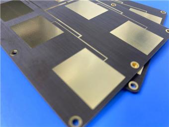
Taconic TLX-8 PCB 50mil ENIG 2-Layer High-Frequency RF Circuit Board
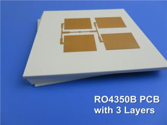
Multilayer high frequency PCBs are made from all high frequency material inclusive of prepreg adhesive.
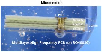
5 layer PCB is fabricated on 3 cores of RO4003C and etched 1 layer copper off to achieve 5 layers.
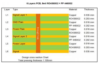
RO4360G2 laminates extend Rogers' portfolio of high performance materials by providing customers with a product that is lead-free process capable and offers better rigidity for improved processability in multi-layer board constructions, while reducing material and fabrication costs.
Megtron 6 is an ultra-low loss, highly heat resistant circuit board material designed for mobile, networking, and wireless applications etc.
This type of 4-layer circuit board is built on Panasonic Megtron6 (M6) R-5775G high speed low loss material.
TU-768 / TU-768P laminate / prepreg are made of high quality woven E-glass coated with the epoxy resin system, which provides the laminates with UV-block characteristic, and compatibility with automated optical inspection (AOI) process.
IT-180ATC is an advanced high Tg (175℃ by DSC) multifunctional filled epoxy with high thermal reliability and CAF resistance.
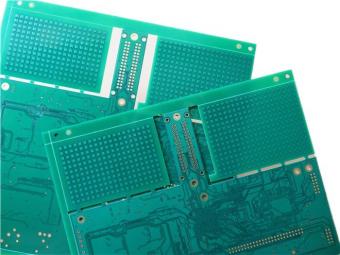
This is a type of 8-layer printed circuit board built on FR-4 Tg175℃ substrate for the application of Satellite Radio.
 6-11C Shidai Jingyuan, Fuyong, Baoan, Shenzhen, Guangdong, China 518103


For inquiries about our products or pricelist, please leave to us and we will be in touch within 24 hours.
© Copyright: 2026 Shenzhen Bicheng Electronics Technology Co., Ltd.. All Rights Reserved.

IPv6 network supported


