

 Call Us Now !
Tel : +86 755 27374946
Call Us Now !
Tel : +86 755 27374946
 Order Online Now !
Email : info@bichengpcb.com
Order Online Now !
Email : info@bichengpcb.com
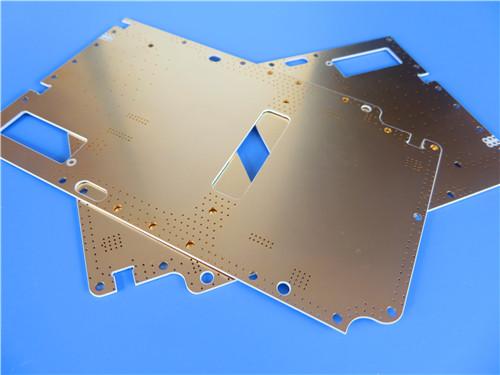
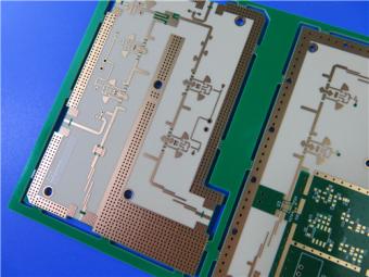
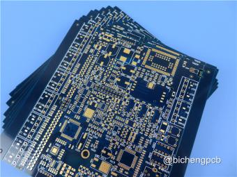
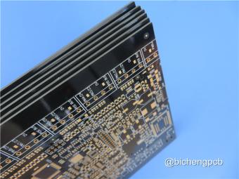
The 4-layer 20mil RO3210 ISIG PCB represents a carefully engineered solution for high-frequency applications requiring a high dielectric constant, low insertion loss, and a clean, mask-free surface.
Item NO.:
BIC-622-v707Order(MOQ):
1-10Payment:
T/TProduct Origin:
ChinaShipping Port:
ShenzhenLead Time:
7-10 days
4-Layer 20milRogersRO3210 ISIG High-Frequency PCB with Controlled Depth Milling
This 4-layer high-frequency multilayer board is engineered on Rogers RO3210 ceramic-filled, woven-glass-reinforced PTFE laminates with a finished board thickness of 1.22 mm. Built around a symmetric stackup of two 0.508 mm (20 mil) RO3210 cores bonded by a 0.2 mm RO4450F prepreg layer, the board delivers a controlled dielectric constant of 10.2 in the signal-carrying core regions while maintaining mechanical rigidity and dimensional stability. With 1 oz finished copper on all four layers, an Immersion Silver + Immersion Gold (ISIG) surface finish, and no solder mask or silkscreen on either side, this board is optimized for high-frequency RF and microwave applications where signal integrity, low insertion loss, and clean surface topography are paramount.
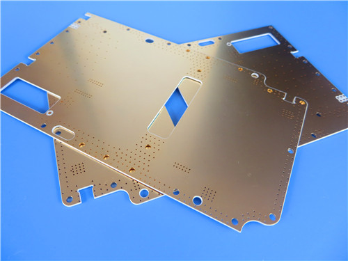
The table below summarizes the complete construction specifications of this 4-layer RO3210 PCB, covering base material, geometry, copper weight, surface finish, and quality assurance parameters.
|
Parameter |
Specification |
|
Base Material |
RO3210 + RO4450F PP |
|
Layer Count |
4 layers |
|
Board Dimensions |
79 mm × 79 mm = 1 PCS |
|
Finished Board Thickness |
1.22 mm |
|
Finished Cu Weight (Outer Layers) |
1 oz |
|
Finished Cu Weight (Inner Layers) |
1 oz |
|
Surface Finish |
Immersion Silver + Immersion Gold (ISIG) |
|
Top Silkscreen |
No |
|
Bottom Silkscreen |
No |
|
Top Solder Mask |
No |
|
Bottom Solder Mask |
No |
|
Controlled Depth Milling (Slot) |
Yes |
|
Electrical Test |
100% prior to shipment |
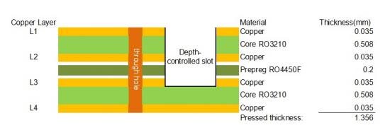
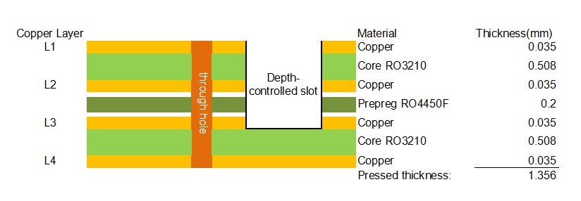
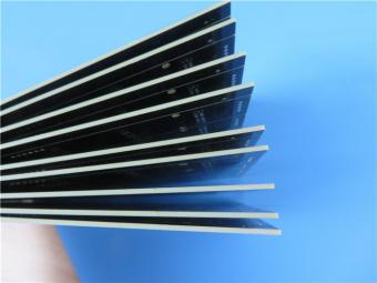
The board employs a symmetric 4-layer stackup with two 0.508 mm RO3210 cores separated by a 0.2 mm RO4450F bonding ply, achieving a total pressed thickness of 1.356 mm. The symmetrical architecture ensures balanced mechanical stress and minimizes bow and twist through thermal cycling.
The selection of RO3210 as the core substrate is driven by its high process dielectric constant of 10.2 (±0.50) at 10 GHz, measured per IPC-TM-650 2.5.5.5 using the clamped stripline method. The design dielectric constant is specified at 10.8 across the 8–40 GHz range via the differential phase length method. This elevated Dk allows designers to realize substantially shorter transmission-line lengths and more compact circuit geometries compared to standard FR-4 (Dk ≈ 4.2) or mid-range microwave laminates such as RO4350B (Dk ≈ 3.48), which is particularly valuable in space-constrained RF front-end modules, power amplifiers, and antenna feed networks. The dissipation factor of 0.0027 at 10 GHz is notably low for a high-Dk material, ensuring low insertion loss and preserving signal power at microwave frequencies.
The RO4450F prepreg, with a Dk of 3.52 (±0.05) and Df of 0.004 at 10 GHz, serves as the interlayer bonding material between the two RO3210 cores. While its Dk is substantially lower than the core material, this is a deliberate and common multilayer design strategy: the prepreg primarily provides interlayer adhesion and mechanical bonding rather than serving as a controlled-impedance dielectric for critical signal lines. The 0.2 mm prepreg thickness provides sufficient resin volume to ensure void-free lamination while maintaining the overall thickness target. The "F" designation in RO4450F indicates an optimized resin rheology with enhanced lateral flow during the lamination heat cycle, which improves wet-out and reduces the risk of micro-voids or delamination during multilayer pressing.
The symmetric stackup — RO3210 core / RO4450F PP / RO3210 core — ensures balanced mechanical stress across the board, minimizing bow and twist during fabrication and assembly. This symmetry is critical for boards that undergo lead-free reflow profiles, where CTE mismatches between layers can induce warpage. RO3210 exhibits an in-plane CTE of 13 ppm/°C (X-Y), close to that of copper (17 ppm/°C), further reducing thermally induced stress on plated through-holes and solder joints.
This multilayer Rogers board features a dual Immersion Silver + Immersion Gold (ISIG) surface finish, a configuration selected to address specific high-frequency performance requirements. Immersion silver provides a flat, coplanar surface with excellent high-frequency signal characteristics — silver has the highest electrical conductivity of any metal (6.30 × 10⁷ S/m at 20°C), minimizing skin-effect losses at microwave frequencies. The immersion gold overlayer provides oxidation resistance and solderability, protecting the silver surface from tarnish and handling damage during storage and PCBA assembly.
Unlike conventional ENIG (Electroless Nickel Immersion Gold) finishes, the ISIG combination avoids a nickel layer under the gold. Nickel is ferromagnetic and has substantially lower conductivity than silver or copper, introducing additional signal attenuation at frequencies above approximately 5–10 GHz where skin depth becomes very small. By eliminating nickel from the signal path, ISIG preserves the low-loss characteristics critical for X-band and Ku-band circuitry. The absence of solder mask and silkscreen on both top and bottom sides is equally intentional: solder mask can introduce additional dielectric loading and surface roughness that degrade high-frequency performance, particularly on exposed transmission lines, couplers, and antenna elements. A bare, ISIG-finished copper surface provides the most electrically clean environment for RF signal propagation.
The board incorporates controlled depth milling (slot), a precision machining process that creates cavities or recesses at a specified depth without penetrating the entire board thickness. This feature is commonly used for component recessing (e.g., lowering the profile of tall RF components), impedance tuning in cavity-backed structures, or creating shielded compartments within RF assemblies. Controlled depth routing requires tight tolerance control over milling depth, typically achieved through precision CNC routing with real-time depth monitoring, ensuring that the remaining dielectric thickness meets design specifications for both signal integrity and structural integrity.
This 4-layer RO3210 ISIG PCB is well-suited for a range of high-frequency applications including:
RF and microwave power amplifiers;
Antenna feed networks and phased array radar modules;
Satellite communication subsystems;
Point-to-point microwave radio links operating at X-band and Ku-band;
Test and measurement equipment;
Aerospace and defense electronics requiring high-Dk, low-loss substrates with mask-free high-frequency surfaces.
The 4-layer 20mil RO3210 ISIG PCB represents a carefully engineered solution for high-frequency applications requiring a high dielectric constant, low insertion loss, and a clean, mask-free surface. Its symmetric RO3210/RO4450F/RO3210 stackup delivers mechanical stability and predictable electrical performance, while the ISIG surface finish minimizes conductor losses by eliminating the nickel layer present in conventional ENIG processes. With 1 oz copper on all layers, controlled depth milling capability, and 100% electrical test coverage, this board combines premium material performance with manufacturing precision to meet the demands of modern RF and microwave circuit design.
Part 2: RO3210 Copper Clad Laminate — Material Deep Dive
RO3210 is a ceramic-filled, woven-glass-reinforced PTFE (polytetrafluoroethylene) high-frequency circuit laminate manufactured by Rogers Corporation. It belongs to the RO3200 series, which was developed as an extension of the RO3000® series with one distinguishing characteristic — improved mechanical stability. RO3210 combines the surface smoothness of a non-woven PTFE laminate, enabling finer line etching tolerances, with the rigidity and dimensional stability of a woven-glass PTFE laminate. These materials can be fabricated into printed circuit boards using standard PTFE circuit board processing techniques as described in Rogers' application note, "Fabrication Guidelines for RO3000 Series High Frequency Circuit Materials." RO3200 series laminates are manufactured under an ISO 9002 certified quality system.
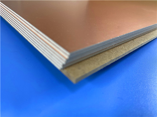
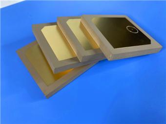
Figure 1: RO3210 Copper Clad Laminate
The table below presents the complete typical property values for RO3210 as specified in the official Rogers datasheet (Publication 92-109, Revised 080619), covering electrical, mechanical, thermal, and physical characteristics. All values are tested at 23°C unless otherwise noted.
|
Property |
Typical Value |
Direction |
Unit |
Condition |
Test Method |
|
Dielectric Constant (Process, εr) |
10.2 ± 0.50 |
Z |
— |
10 GHz, 23°C |
IPC-TM-650 2.5.5.5 Clamped Stripline |
|
Dielectric Constant (Design, εr) |
10.8 |
Z |
— |
8–40 GHz |
Differential Phase Length Method |
|
Dissipation Factor (tan δ) |
0.0027 |
Z |
— |
10 GHz, 23°C |
IPC-TM-650 2.5.5.5 |
|
Thermal Coefficient of εr |
-459 |
Z |
ppm/°C |
10 GHz, 0–100°C |
IPC-TM-650 2.5.5.5 |
|
Dimensional Stability |
0.8 |
X, Y |
mm/m |
COND A |
ASTM D257 |
|
Volume Resistivity |
10³ |
— |
MΩ·cm |
COND A |
IPC 2.5.17.1 |
|
Surface Resistivity |
10³ |
— |
MΩ |
COND A |
IPC 2.5.17.1 |
|
Tensile Modulus |
579 / 517 |
MD / CMD |
kpsi |
23°C |
ASTM D638 |
|
Water Absorption |
<0.1 |
— |
% |
D24/23 |
IPC-TM-650 2.6.2.1 |
|
Specific Heat |
0.79 |
— |
J/g/K |
— |
Calculated |
|
Thermal Conductivity |
0.81 |
— |
W/m/K |
80°C |
ASTM C518 |
|
CTE (-55 to 288°C) |
13 / 34 |
X,Y / Z |
ppm/°C |
23°C / 50% RH |
IPC-TM-650 2.4.41 |
|
Decomposition Temperature (Td) |
500 |
— |
°C |
TGA |
ASTM D3850 |
|
Color |
Off White |
— |
— |
— |
— |
|
Density |
3.0 |
— |
gm/cm³ |
— |
— |
|
Copper Peel Strength |
11.0 |
— |
pli |
1 oz EDC, After Solder Float |
IPC-TM-2.4.8 |
|
Flammability |
V-0 |
— |
— |
— |
UL 94 |
|
Lead-Free Process Compatible |
YES |
— |
— |
— |
— |
The following table lists the standard available thicknesses, panel sizes, and copper cladding options for RO3210 high DK laminates as specified by Rogers Corporation.
|
Category |
Specification |
|
Standard Thickness |
0.025" (0.64 mm), 0.050" (1.28 mm) |
|
Standard Panel Size |
12" × 18" (305 × 457 mm), 24" × 18" (610 × 457 mm) |
|
Standard Copper Cladding |
½ oz (17 µm) ED copper (HH/HH); 1 oz (35 µm) ED copper (H1/H1); 2 oz (70 µm) ED copper (H2/H2) |
|
Other Claddings |
May be available — contact Rogers customer service |
RO4450F is a hydrocarbon-ceramic prepreg (bonding ply) used as the interlayer bonding material in this multilayer construction. Key properties include: dielectric constant of 3.52 ± 0.05 at 10 GHz (Z-direction, IPC-TM-650 2.5.5.5); dissipation factor of 0.004 at 10 GHz; thermal conductivity of 0.65 W/m/K; glass transition temperature (Tg) of 280°C; standard thickness of 0.004" (0.102 mm) per ply; UL 94 V-0 flammability rating; and lead-free process compatibility.
The "F" designation indicates enhanced resin flow characteristics, which improves lamination yield by reducing void entrapment and ensuring complete resin wet-out during the multilayer press cycle. In this board design, the 0.2 mm RO4450F layer provides the bonding interface between the two RO3210 cores, with its lower Dk serving as a non-critical interlayer dielectric while its hydrocarbon-ceramic chemistry ensures compatibility with the PTFE-based cores.
RO3210 is a specialized high-Dk, low-loss PTFE laminate that fills a unique niche in the high-frequency PCB material landscape. Its combination of Dk 10.2, Df 0.0027, woven-glass mechanical stability, and lead-free process compatibility makes it a preferred choice for compact, high-performance RF and microwave circuits.
When paired with RO4450F prepreg for multilayer constructions, designers can achieve symmetric, reliable stackups that leverage the high-Dk core for signal routing while using the lower-Dk bonding ply for interlayer adhesion. The material's well-documented properties, standardized thickness options, and ISO 9002-certified manufacturing provide the consistency and traceability required for demanding aerospace, defense, and telecommunications applications.





Previous:
4-Layer Rogers RO3010 Hybrid PCB Immersion Silver 2.8mm Finished ThicknessNext:
4-Layer 8mil RO4003C + RO4450F Rogers High Frequency PCB with Immersion Gold 2 u"If you have questions or suggestions,please leave us a message,we will reply you as soon as we can!
Categories
New Products
10-Layer RO4350B + TU-768 Hybrid PCB with Via Copper Capped ENIG Surface Finish
8-Layer 6.6mil Rogers RO4350B + Isola I-Tera MT40 Hybrid PCB 1.636mm Pressed Thickness ENEPIG
6-Layer 5mil Rogers RO3003 Mixed-Laminated with Isola 370HR 0.82 mm Hybrid PCB with ENIG
4-Layer 8mil RO4003C + Tg170 FR-4 Hybrid PCB with ENIG — 0.556mm Thin Build
1100 × 350mm Long-Format Rogers RO4003C 32 mil core Double-Sided High-Frequency PCB
Wangling TP2200 PCB 0.8mm Substrate Immersion Gold 2-Layer High-Dk (Dk 22) RF Board
Rogers TMM10 PCB 5.08mm Core ENIG 2-Layer High-Dk Microwave Board
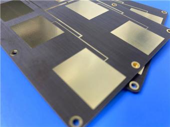
Taconic TLX-8 PCB 50mil ENIG 2-Layer High-Frequency RF Circuit Board
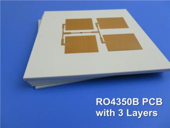
Multilayer high frequency PCBs are made from all high frequency material inclusive of prepreg adhesive.
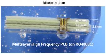
5 layer PCB is fabricated on 3 cores of RO4003C and etched 1 layer copper off to achieve 5 layers.
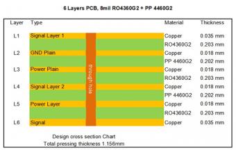
RO4360G2 laminates extend Rogers' portfolio of high performance materials by providing customers with a product that is lead-free process capable and offers better rigidity for improved processability in multi-layer board constructions, while reducing material and fabrication costs.
Megtron 6 is an ultra-low loss, highly heat resistant circuit board material designed for mobile, networking, and wireless applications etc.
This type of 4-layer circuit board is built on Panasonic Megtron6 (M6) R-5775G high speed low loss material.
TU-768 / TU-768P laminate / prepreg are made of high quality woven E-glass coated with the epoxy resin system, which provides the laminates with UV-block characteristic, and compatibility with automated optical inspection (AOI) process.
IT-180ATC is an advanced high Tg (175℃ by DSC) multifunctional filled epoxy with high thermal reliability and CAF resistance.
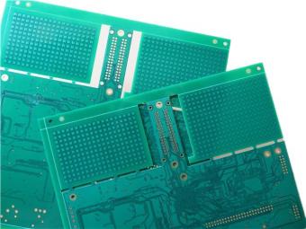
This is a type of 8-layer printed circuit board built on FR-4 Tg175℃ substrate for the application of Satellite Radio.
 6-11C Shidai Jingyuan, Fuyong, Baoan, Shenzhen, Guangdong, China 518103


For inquiries about our products or pricelist, please leave to us and we will be in touch within 24 hours.
© Copyright: 2026 Shenzhen Bicheng Electronics Technology Co., Ltd.. All Rights Reserved.

IPv6 network supported


