

 Call Us Now !
Tel : +86 755 27374946
Call Us Now !
Tel : +86 755 27374946
 Order Online Now !
Email : info@bichengpcb.com
Order Online Now !
Email : info@bichengpcb.com

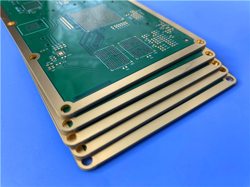
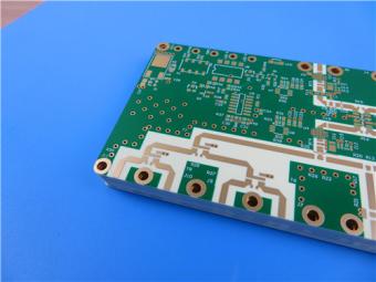
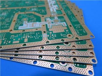
This 4-layer 10 mil RO3003 + Tg170 FR-4 hybrid PCB represents a carefully engineered solution that balances high-frequency electrical performance with cost-effective manufacturing.
Item NO.:
BIC-621-v706Order(MOQ):
1-10Payment:
T/TProduct Origin:
ChinaShipping Port:
ShenzhenLead Time:
7-10 days
4-Layer 10mil RO3003 + Tg170 FR-4 Hybrid PCB with ENIG and Controlled Depth Milling
Product Specification & Technical Overview
This 4-layer hybrid printed circuit board combines Rogers RO3003 high-frequency laminate (10 mil core) with Tg170 FR-4 prepreg to deliver a cost-effective solution for RF and mixed-signal applications. The hybrid architecture leverages RO3003's exceptional dielectric stability (Dk 3.00 ± 0.04, Df 0.0010 at 10 GHz) for critical high-frequency signal layers, while FR-4 Tg170 provides robust mechanical support and cost efficiency for the remaining dielectric layers. With a finished board thickness of 0.694 mm, 1 oz copper on all four layers, and Immersion Gold (ENIG) surface finish, this Rogers RO3003 hybrid PCB is engineered for applications requiring reliable high-frequency performance alongside standard digital circuitry.
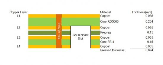
The following table summarizes the complete construction specifications for this 4-layer hybrid PCB, covering material composition, dimensional parameters, surface finishing, and quality assurance requirements.
|
Parameter |
Specification |
|
Base Material |
RO3003 (10 mil) + Tg170 FR-4 (Hybrid Laminate) |
|
Layer Count |
4 Layers |
|
Board Dimensions |
127 mm × 97 mm = 5 designs = 5 PCS, ±0.15 mm |
|
Finished Board Thickness |
0.694 mm (after lamination) |
|
Finished Cu Weight |
1 oz (35 μm / 1.4 mil) on all 4 layers |
|
Surface Finish |
Immersion Gold (ENIG) |
|
Top Silkscreen |
White |
|
Bottom Silkscreen |
White |
|
Top Solder Mask |
Green |
|
Bottom Solder Mask |
Green |
|
Controlled Depth Milling |
L2–L4, no plating required |
|
Electrical Test |
100% Electrical test prior to shipment |
Table 1: PCB Construction Details
The layer stackup below details the material and thickness allocation for each layer. The 10 mil RO3003 core is positioned between L2 and L3 as the primary high-frequency dielectric, while Tg170 FR-4 prepreg fills the L1–L2 and L3–L4 gaps to achieve the total finished thickness of 0.694 mm.
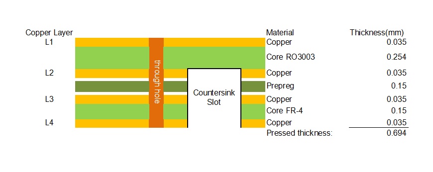
Table 2: PCB Layer Stackup (Total Thickness: 0.694 mm)
The defining feature of this PCB is its hybrid dielectric construction. The 10 mil RO3003 core serves as the central high-frequency layer pair (L2/L3), providing a tightly controlled dielectric constant of 3.00 with a tolerance of ±0.04 and an ultra-low dissipation factor of 0.0010 at 10 GHz. These properties ensure minimal signal attenuation and consistent impedance control for RF traces routed on the inner layers. The thermal coefficient of dielectric constant for RO3003 is only -3 ppm/°C across -50°C to 150°C, meaning that electrical performance remains stable even under extreme temperature fluctuations—a critical requirement for automotive and aerospace applications.
The outer layer pairs (L1–L2 and L3–L4) use Tg170 FR-4 prepreg, which offers a glass transition temperature of 170°C, providing excellent thermal reliability for lead-free assembly processes while significantly reducing material cost compared to an all-RO3003 construction.
This hybrid approach allows designers to place high-frequency critical paths on the RO3003 core while routing standard digital and power signals on layers adjacent to FR-4, achieving an optimal balance of performance and cost. Furthermore, because RO3003's mechanical properties are consistent across the RO3000 family regardless of dielectric constant, this hybrid construction can be extended to designs that combine multiple Dk materials in a single multilayer stack without warpage or reliability concerns—offering designers significant architectural flexibility.
A specialized fabrication feature of this PCB is the controlled depth milling (also known as depth-controlled routing or cavity milling) from Layer 2 through Layer 4, performed without subsequent plating. This process creates precise recessed cavities or slots at a controlled depth, stopping at or between specific inner layers without penetrating the entire board. Controlled depth milling is commonly used for applications requiring component recessing (such as chip-on-board packaging or module integration), impedance tuning cavities, or thermal management features. The "no plating" specification means that the milled cavity walls remain uncoated, which is appropriate when the cavity is used for mechanical positioning or non-conductive isolation rather than electrical interconnection.
This feature requires tight process control during fabrication to ensure consistent depth accuracy across all five board designs, and it adds a differentiated capability that distinguishes this PCB from standard 4-layer constructions.
The PCB features an Immersion Gold (ENIG) surface finish, which deposits a thin layer of nickel (typically 3–5 μm) followed by an ultra-thin gold layer (typically 0.05–0.15 μm) over exposed copper pads. ENIG provides a flat, coplanar surface ideal for fine-pitch SMT components and BGA packages, as it does not suffer from the surface irregularities associated with HASL (Hot Air Solder Leveling).
The gold layer protects the nickel from oxidation, providing excellent shelf life (typically 6–12 months) and consistent solderability. Additionally, ENIG is suitable for wire bonding and press-fit connectors, making it a versatile choice for mixed-technology assemblies. Compared to other surface finishes such as OSP (Organic Solderability Preservative), ENIG offers superior durability for multiple reflow cycles and is well-suited for high-reliability applications.
This 4-layer Hybrid PCB Board is well-suited for a range of applications that require high-frequency signal integrity alongside cost-effective digital integration. The combination of RO3003's low-loss dielectric with FR-4's structural economy makes it particularly attractive for volume production where all-PTFE construction would be prohibitively expensive. Primary application areas include:
• Automotive Radar & ADAS
• Satellite Communications
• 5G / mmWave Infrastructure
• Test & Measurement Equipment
• Aerospace & Defense
In summary, this 4-layer 10 mil RO3003 + Tg170 FR-4 hybrid PCB represents a carefully engineered solution that balances high-frequency electrical performance with cost-effective manufacturing.
The RO3003 core delivers exceptional dielectric stability (Dk 3.00 ± 0.04, Df 0.0010) and thermal reliability, while the FR-4 Tg170 prepreg provides structural support and material cost optimization. Key differentiators include controlled depth milling from L2 to L4 without plating, ENIG surface finish for superior assembly compatibility, uniform 1 oz copper across all layers.
With a finished thickness of 0.694 mm and board dimensions of 127 mm × 97 mm across five designs, this PCB is ready for integration into automotive radar, satellite communications, 5G infrastructure, and test & measurement applications where reliable high-frequency performance is non-negotiable.
Part 2: CCL Material Knowledge — RO3003 High Frequency Laminate
RO3003 is a high-frequency circuit laminate from the Rogers RO3000 series, engineered specifically for commercial microwave and RF applications. As a ceramic-filled PTFE (polytetrafluoroethylene) composite, RO3003 offers a dielectric constant of 3.00 with an ultra-low dissipation factor of 0.0010 at 10 GHz, making it one of the most widely used high-frequency laminates in the industry.
The RO3000 series was designed to provide exceptional electrical and mechanical stability at competitive prices, filling the gap between expensive pure PTFE substrates and lower-performance FR-4 materials. RO3003 is particularly valued for its tight Dk tolerance (±0.04) and excellent thermal coefficient of dielectric constant (-3 ppm/°C), which ensure that circuit performance remains consistent across temperature variations and production lots.
RO3003 is constructed from a PTFE polymer matrix reinforced with ceramic filler particles. The ceramic filler serves two critical functions: it raises and stabilizes the dielectric constant, and it improves the mechanical rigidity and dimensional stability of the material—addressing the inherent softness and high CTE of unfilled PTFE. The result is a composite that retains PTFE's excellent electrical properties (low loss, low moisture absorption) while gaining mechanical properties more comparable to conventional FR-4.
A key advantage of the RO3000 series family is that mechanical properties remain consistent regardless of the dielectric constant selected. This allows designers to develop multilayer board designs that use different dielectric constant materials for individual layers—such as combining RO3003 (Dk 3.0) with RO3010 (Dk 10.2)—without encountering warpage or reliability problems. RO3003 is available with both electrodeposited (ED) and rolled copper foil cladding in ½ oz (18 μm) and 1 oz (35 μm) weights, providing flexibility for different circuit designs and manufacturing requirements.
The following table presents the complete standard properties for RO3003 laminate, including electrical, thermal, mechanical, and physical characteristics with corresponding test conditions and test methods. All values are typical unless otherwise specified.
|
Property |
RO3003 Value |
Units |
Test Conditions |
Test Method |
|
Dielectric Constant (process) |
3.00 ± 0.04 |
- |
23°C, 10 GHz |
IPC TM-650 2.5.5.5 |
|
Dielectric Constant (design) |
3.00 |
- |
8 GHz – 40 GHz |
Differential Phase Length |
|
Dissipation Factor |
0.0010 |
- |
23°C, 10 GHz |
IPC TM-650 2.5.5.5 |
|
Thermal Coefficient of Dk |
-3 |
ppm/°C |
-50 to 150°C, 10 GHz |
IPC TM-650 2.5.5.5 |
|
Volume Resistivity |
10⁷ |
MΩ·cm |
Condition A |
IPC TM-650 2.5.17.1 |
|
Surface Resistivity |
10⁷ |
MΩ |
Condition A |
IPC TM-650 2.5.17.1 |
|
Decomposition Temperature (Td) |
500 |
°C |
TGA |
ASTM D3850 |
|
CTE – X axis |
17 |
ppm/°C |
-55 to 288°C |
IPC TM-650 2.4.41 |
|
CTE – Y axis |
16 |
ppm/°C |
-55 to 288°C |
IPC TM-650 2.4.41 |
|
CTE – Z axis |
25 |
ppm/°C |
-55 to 288°C |
IPC TM-650 2.4.41 |
|
Thermal Conductivity |
0.50 |
W/(m·K) |
50°C |
ASTM D5470 |
|
Copper Peel Strength |
12.7 |
lbs/in |
1 oz ED, after solder float |
IPC TM-650 2.4.8 |
|
Young's Modulus |
930 / 823 |
MPa |
23°C |
ASTM D638 |
|
Dimensional Stability (MD/CMD) |
-0.06 / 0.07 |
mm/m |
Condition A |
IPC TM-650 2.2.4 |
|
Flammability |
V-0 |
- |
- |
UL 94 |
|
Moisture Absorption |
0.04 |
% |
D48/50 |
IPC TM-650 2.6.2.1 |
|
Density |
2.1 |
g/cm³ |
23°C |
ASTM D792 |
|
Specific Heat Capacity |
0.9 |
J/g/K |
- |
Calculated |
|
Lead-Free Process Compatible |
Yes |
- |
- |
- |
Table 3: RO3003 Standard Properties Datasheet (Source: Rogers Corporation)
RO3003 specifies a process dielectric constant of 3.00 ± 0.04 measured at 23°C and 10 GHz per IPC TM-650 2.5.5.5, and a design dielectric constant of 3.00 validated across 8 GHz to 40 GHz using the differential phase length method. The tight ±0.04 tolerance (approximately ±1.3%) is significantly tighter than typical FR-4 (which often ranges ±5–10%), ensuring that impedance-controlled transmission lines fabricated on RO3003 meet target characteristic impedance with high yield.
The dissipation factor of 0.0010 at 10 GHz is approximately 15–20 times lower than standard FR-4 (Df ~0.015–0.020), translating directly into lower insertion loss for high-frequency signal paths. For a 50 Ω microstrip line on 10 mil RO3003, the conductor and dielectric losses remain well below those of equivalent FR-4 designs, making RO3003 suitable for applications where signal power efficiency is critical.
One of the most important electrical characteristics of RO3003 is its thermal coefficient of dielectric constant of only -3 ppm/°C across the range of -50°C to 150°C. This means that over a 200°C temperature swing, the dielectric constant changes by less than 0.06%—a level of stability that is essential for frequency-sensitive circuits such as oscillators, filters, and antennas where even small Dk shifts can cause resonant frequency drift. In contrast, conventional PTFE-glass materials exhibit a noticeable step change in dielectric constant near room temperature due to the PTFE glass transition, which RO3003's ceramic-filled formulation effectively eliminates. Chart 1 below illustrates the excellent Dk stability of RO3003 compared to PTFE/glass and RO3035 laminates over temperature.
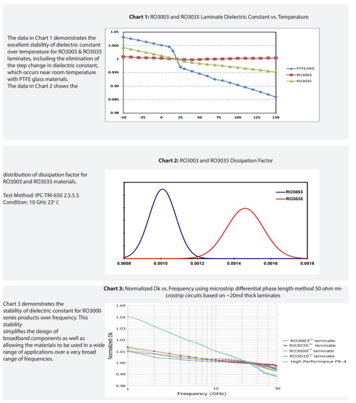
Figure 1: RO3003 Property Charts — Dk vs. Temperature (Chart 1), Dissipation Factor Distribution (Chart 2), and Normalized Dk vs. Frequency (Chart 3) (Source: Rogers Corporation)
Chart 3 in Figure 1 demonstrates the stability of dielectric constant for RO3000 series products over frequency. Using the microstrip differential phase length method on 50 Ω microstrip circuits based on ~20 mil thick laminates, the normalized Dk of RO3003 remains exceptionally flat from 1 GHz to 50 GHz. This frequency stability simplifies the design of broadband components and allows the material to be used in a wide range of applications over a very broad frequency spectrum. For designers working across multiple frequency bands—such as dual-band 5G front-ends covering sub-6 GHz and mmWave—the flat Dk response means that a single material specification can serve both bands without requalification.
RO3003 is available in a range of standard thicknesses, panel sizes, and copper cladding options to accommodate diverse design requirements. The table below summarizes the standard configurations. Additional thicknesses, panel sizes, and claddings may be available by contacting Rogers Customer Service or Sales Engineering.
|
Category |
Standard Options |
|
Standard Thicknesses |
0.005" (0.13 mm) ±0.0005" 0.010" (0.25 mm) ±0.0007" 0.020" (0.51 mm) ±0.0010" 0.030" (0.76 mm) ±0.0015" 0.060" (1.52 mm) ±0.0030" |
|
Standard Panel Sizes |
12" × 18" (305 × 457 mm) 24" × 18" (610 × 457 mm) |
|
Standard Cladding |
Electrodeposited Copper Foil: ½ oz (18 μm), 1 oz (35 μm) Rolled Copper Foil: ½ oz (18 μm), 1 oz (35 μm) |
Table 4: RO3003 Available Configurations (Source: Rogers Corporation)
RO3003 is widely adopted in automotive radar systems operating at 77 GHz and 79 GHz bands for adaptive cruise control (ACC), automatic emergency braking (AEB), blind spot detection (BSD), and other ADAS functions. The material's tight Dk tolerance and low Df ensure accurate radar beamforming and minimal signal loss in compact antenna arrays, while its -3 ppm/°C thermal coefficient of Dk guarantees consistent radar performance across the extreme temperature ranges encountered in automotive environments (-40°C to +85°C or higher under hood). The CTE matching to copper also provides excellent PTH reliability for the thermal cycling demands of automotive qualification (AEC-Q200 / AEC-Q104).

Figure 2: Automotive Radar / ADAS Application (Source: Rogers Corporation)
In satellite communications, RO3003 is used in antenna feed networks, low-noise block (LNB) downconverters, phased array antennas, and ground station equipment operating at C-band, X-band, Ku-band, and Ka-band frequencies. The ultra-low dissipation factor minimizes signal attenuation in receive paths, improving system noise figure and sensitivity. The excellent dimensional stability (etch shrinkage < 0.5 mil/inch) ensures that antenna array element spacing remains precise, which is critical for achieving designed beam patterns and sidelobe levels. RO3003's low moisture absorption (0.04%) also ensures that outdoor ground station and satellite terminal equipment maintains stable electrical performance in humid and condensing environments.

Figure 3: Satellite Communications Antenna Application (Source: Rogers Corporation)
RO3003 high-frequency laminate from the Rogers RO3000 series represents a mature, well-characterized solution for commercial microwave and RF applications requiring a dielectric constant of 3.00. Its ceramic-filled PTFE composition delivers an exceptional combination of electrical performance (Dk 3.00 ± 0.04, Df 0.0010 at 10 GHz), thermal stability (Td 500°C, TCDk -3 ppm/°C), and mechanical reliability (CTE matched to copper, 12.7 lbs/in peel strength, UL 94 V-0).
The material's consistent mechanical properties across the RO3000 family enable hybrid multilayer designs that combine different Dk materials without warpage issues. Available in five standard thicknesses from 0.13 mm to 1.52 mm, two panel sizes, and both ED and rolled copper cladding, RO3003 offers designers the flexibility to optimize for specific frequency, impedance, and power requirements.
When combined with FR-4 Tg170 prepreg in a hybrid construction—as in the 4-layer PCB described in Part 1—RO3003 provides the high-frequency performance where it is needed most while the overall design remains cost-competitive for high-volume commercial applications including automotive radar, satellite communications, 5G infrastructure, and test & measurement equipment.





Previous:
8-Layer Hybrid RF PCB: RO4350B + TG170 FR-4 + RO4003C with RO4450F BondplyNext:
6-Layer 10mil RO4350B + IT180A Hybrid PCB with ENIG Blind Via Edge PlatingIf you have questions or suggestions,please leave us a message,we will reply you as soon as we can!
Categories
New Products
10-Layer RO4350B + TU-768 Hybrid PCB with Via Copper Capped ENIG Surface Finish
8-Layer 6.6mil Rogers RO4350B + Isola I-Tera MT40 Hybrid PCB 1.636mm Pressed Thickness ENEPIG
6-Layer 5mil Rogers RO3003 Mixed-Laminated with Isola 370HR 0.82 mm Hybrid PCB with ENIG
4-Layer 8mil RO4003C + Tg170 FR-4 Hybrid PCB with ENIG — 0.556mm Thin Build
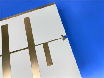
1100 × 350mm Long-Format Rogers RO4003C 32 mil core Double-Sided High-Frequency PCB
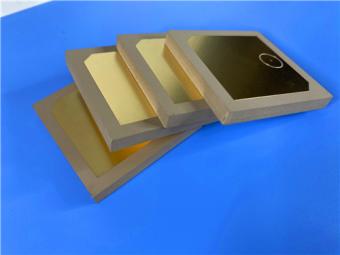
Wangling TP2200 PCB 0.8mm Substrate Immersion Gold 2-Layer High-Dk (Dk 22) RF Board
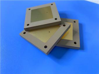
Rogers TMM10 PCB 5.08mm Core ENIG 2-Layer High-Dk Microwave Board
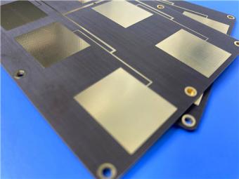
Taconic TLX-8 PCB 50mil ENIG 2-Layer High-Frequency RF Circuit Board
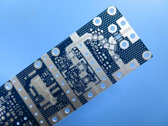
RO4003C exhibit a stable dielectric constant over a broad frequency range. This makes it an ideal substrate for broadband applications. And signal integrity performance improvement over the stack-ups with all FR4 board.
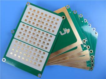
The hybrid PCB can be a mixture of FR-4 and high frequency material, and a mixture of high frequency material with different dielectric constant (DK)
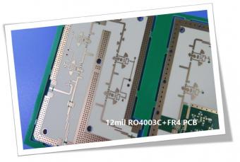
The 12mil core is on the top layer and it mainly plays the roles of signal layer. The core has fixed thickness which is very important to the electrical length of RF lines on the circuit board.
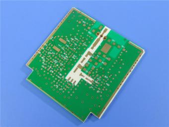
The hybrid PCB can be a mixture of FR-4 and high frequency material as abovementioned.
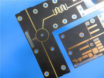
It contains 2 different boards in the panel. PCB boards are manufactured strictly as per required specifications with the standard IPC-Class-II.
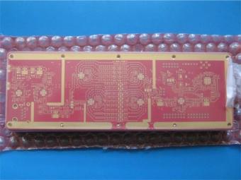
Hybrid PCB is also known as mixed material lamination, it’s normally combined by two different material like FR4 and PI(rigid flex PCB), FR4 and Ceramic, FR4 and Teflon, FR4 and Aluminum base etc.
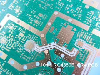
Hybrid constructions PCB typically involve a low loss material such as Nelco or Rogers combined with another core material like FR-4.
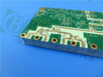
The Hybrid PCB on RO3003 and High Tg FR-4 is a state-of-the-art solution for high-frequency applications. With its exceptional stability, reliability, and manufacturability, it caters to the demands of industries such as automotive, telecommunications, and satellite communications.
 6-11C Shidai Jingyuan, Fuyong, Baoan, Shenzhen, Guangdong, China 518103


For inquiries about our products or pricelist, please leave to us and we will be in touch within 24 hours.
© Copyright: 2026 Shenzhen Bicheng Electronics Technology Co., Ltd.. All Rights Reserved.

IPv6 network supported


