

 Call Us Now !
Tel : +86 755 27374946
Call Us Now !
Tel : +86 755 27374946
 Order Online Now !
Email : info@bichengpcb.com
Order Online Now !
Email : info@bichengpcb.com

The TFA294 high frequency PCB with Immersion Silver Finish represents a carefully optimized convergence of advanced material science and precision manufacturing. Its ceramic-filled PTFE dielectric eliminates the fiberglass weave effect, delivering exceptionally stable Dk and Df across temperature extremes and frequencies up to 77GHz.
Item NO.:
BIC-580-v665.0Order(MOQ):
1-10Payment:
T/TProduct Origin:
ChinaShipping Port:
ShenzhenLead Time:
7-10 days
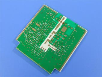
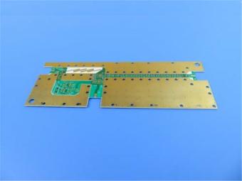
Wangling TFA294 Laminate 40mil Immersion Silver No Solder Mask Silkscreen Custom PCB
1. Product Overview
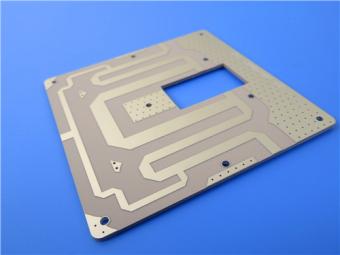
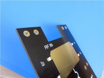
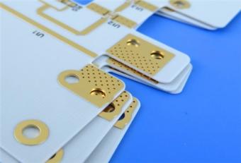
This 40mil TFA294 rigid double-sided board is a custom aerospace-grade high-frequency RF circuit optimized for microwave, radar, satellite communication and phased array antenna systems. Manufactured on glass-fiber-free nano-ceramic filled PTFE composite CCL with immersion silver surface finish, the board strictly complies with IPC-Class-2 reliability standards and undergoes 100% full electrical continuity testing before global shipment. Distinct from conventional glass-reinforced PTFE or FR4 high-frequency boards, the TFA294 substrate eliminates fiberglass electromagnetic distortion (fiberglass effect), delivering ultra-stable dielectric constant across 0.5–77GHz and ultra-low signal loss at millimeter wave bands.
The design omits solder mask and silkscreen on both top and bottom sides to eradicate parasitic capacitance and insertion loss interference critical for phase-sensitive RF circuits, paired with fine-line 4/6mil trace/space geometry and 1oz RTF outer copper foil for minimized conductor loss.
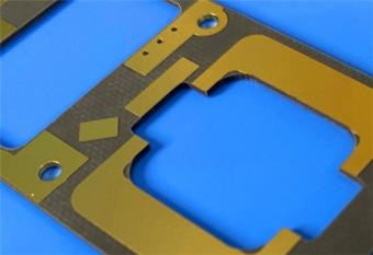
The immersion silver surface finish delivers superior high-frequency conductivity compared to ENIG while maintaining consistent solderability for through-hole and SMT component assembly. This Wangling board is engineered for low-anisotropy, wide-temperature operation (-55°C to 150°C) and long-term vacuum aerospace compatibility, making it a domestically manufacturable alternative to imported foreign high-frequency laminates.
2. PCB Construction Details
The following table summarizes the critical dimensional and manufacturing specifications that define this precision-engineered PCB.
|
Parameter |
Specification |
|
Board Dimensions |
97.53 mm × 100.28 mm per panel, ±0.15 mm |
|
Minimum Trace / Space |
4 mil / 6 mil |
|
Minimum Hole Size |
0.35 mm |
|
Blind Vias |
None |
|
Finished Board Thickness |
1.1 mm (approximately 43.3 mils) |
|
Finished Copper Weight |
1 oz (1.4 mils / 35 µm) on both outer layers |
|
Via Plating Thickness |
20 µm |
|
Surface Finish |
ImmersionSilver |
|
Top Silkscreen |
No |
|
Bottom Silkscreen |
No |
|
Top Solder Mask |
No |
|
Bottom Solder Mask |
No |
|
Electrical Test |
100% electrical test prior to shipment |
3. PCB Stackup Configuration
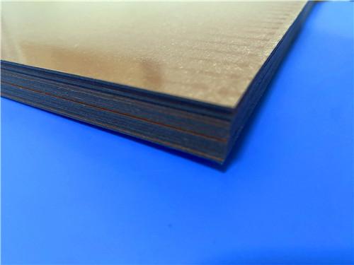
This 2-layer construction features a 1.016mm TFA294 core with symmetric copper foils, providing balanced mechanical stability and excellent Z-axis performance.
|
Layer |
Material |
Thickness |
|
Copper Layer 1 (Top) |
Electro-deposited copper |
35 µm (1 oz) |
|
Dielectric Core |
TFA294 |
1.016 mm (40 mils) |
|
Copper Layer 2 (Bottom) |
Electro-deposited copper |
35 µm (1 oz) |
4. PCB Statistics Summary
The design incorporates 21 components, 32 total pads, and 13 vias across 2 electrical nets–reflecting a compact, highly focused RF circuit layout optimized for minimal parasitic effects.
|
Metric |
Quantity |
|
Components |
21 |
|
Total Pads |
32 |
|
Through-Hole Pads |
18 |
|
Top SMT Pads |
14 |
|
Bottom SMT Pads |
0 |
|
Vias |
13 |
|
Nets |
2 |
5. Differentiated Product Competitive Advantages
5.1 Substrate Material Unique Differentiation
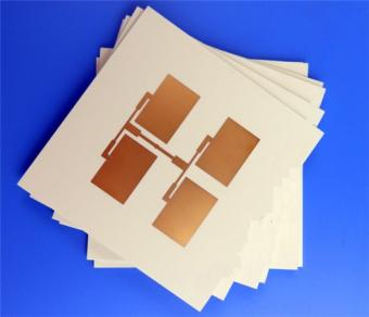
Unlike mainstream glass-fiber woven PTFE laminates (Rogers, Taconic equivalents), Wangling TFA294 CCL abandons glass fiber cloth reinforcement. Uniform nano-ceramic particles are blended evenly with PTFE resin via a proprietary pre-preg and lamination process, eliminating periodic Dk fluctuation caused by glass fiber weave during electromagnetic wave transmission. The material’s X/Y/Z thermal expansion anisotropy is drastically minimized, with X/Y CTE matching copper foil (18ppm/°C), preventing barrel cracking and dimensional drift under wide temperature cycling (-55°C ~ 288°C). For phase-critical antenna and radar beamforming networks, this delivers consistent phase shift stability unavailable from glass-reinforced PTFE substrates.
5.2 Electrical Performance Superiority for High-Frequency Bands
At 10GHz and 20GHz, TFA294 achieves ultra-low dissipation factor Df=0.0010, rising only slightly to 0.0012 at 40GHz; stable Dk=2.94 with tight tolerance±0.04 across production batches. The temperature coefficient of dielectric constant (TCDK) reaches -5ppm/°C within -55°C to 150°C, ensuring minimal signal drift under aerospace thermal cycling. The substrate supports operation up to 77GHz millimeter-wave frequency, covering automotive radar, airborne early warning radar and Ka-band satellite communication bandwidths.
5.3 Immersion Silver Surface Finish Matching RF Requirements
Immersion silver is selected over ENIG for this PCB for targeted high-frequency performance: silver features the highest bulk electrical conductivity among commercial PCB surface metals, eliminating nickel layer signal loss in microwave transmission lines. Without solder mask covering signal traces, the bare copper + immersion silver stack avoids dielectric loss from liquid photoimageable solder mask (LPI), a critical optimization for low-loss power amplifier circuits. The IPC-4553A-compliant silver deposit forms a uniform thin layer (0.12–0.4μm) with fine surface roughness, compatible with tiny SMT pad assembly (14 top SMT pads in this design).
5.4 Mechanical & Environmental Reliability
The TFA294 core features ultra-low moisture absorption of only 0.03%, locking dielectric performance in high-humidity ground station and ocean-borne aerospace environments. UL 94-V0 flame retardant rating meets aerospace cabin fire safety standards, and low outgassing properties satisfy NASA-level vacuum space application requirements. Thermal conductivity of 0.59W/mK delivers passive heat dissipation for medium-power RF amplifier components mounted on the board. The substrate withstands 3 cycles of 260°C / 10s thermal shock without delamination, matching standard lead-free reflow assembly profiles.

6. Typical Applications
This 40mil TFA294 PCB is specifically designed for applications requiring uncompromised RF performance combined with extreme environmental robustness:
6.1 Aerospace & Defense:Spaceborne payloads, airborne radar (AESA), early warning systems, electronic warfare suites, and in-cabin avionics
6.2 Satellite Communications: Ground terminals, satellite transponders, navigation systems (GPS/GNSS), and beamforming networks
6.3 Microwave Systems: High-frequency antennas, passive phase-sensitive arrays, microwave feed networks
6.4 Radar Systems:Airborne fire-control radar, weather radar, surveillance radar, and phased-array radar
6.5 Telecommunications: Millimeter-wave backhaul, 5G mmWave infrastructure, and power amplifiers
7. PCB Conclusion
The TFA294 high frequency PCB with Immersion Silver Finish represents a carefully optimized convergence of advanced material science and precision manufacturing. Its ceramic-filled PTFE dielectric eliminates the fiberglass weave effect, delivering exceptionally stable Dk and Df across temperature extremes and frequencies up to 77GHz. The substrate's CTE matching to copper (18 ppm/°C in-plane, 32 ppm/°C Z-direction) ensures long-term plated through-hole reliability under thermal cycling, while the immersion silver finish provides a low-loss, solderable surface without the magnetic drawbacks of nickel-based finishes.
For engineers and program managers seeking a proven, field-ready solution for aerospace, defense, and millimeter-wave applications, this40mil WanglingPCB delivers the performance, reliability, and traceability demanded by the most stringent mission profiles. Backed by 100% electrical testing, IPC Class-2 compliance, and a worldwide supply chain, this product bridges the gap between laboratory-grade performance and production-scale manufacturability.
Independent Appendix: Detailed Technical Knowledge of TFA294 CCL (Copper-Clad Laminate)
Below is the comprehensive technical datasheet for the TFA294 substrate material, as provided by Taizhou Wangling Insulation Materials Factory. All data was generated in accordance with IPC-TM-650, GB/T 12636-1990, and GBT4722-2017 test methods unless otherwise noted.
1.TFA Series Introduction
TFA series is a proprietary aerospace-grade PTFE ceramic composite copper clad laminate developed by Taizhou Wangling Insulation Material Factory, engineered as a domestic substitute for international high-frequency laminates (Rogers RO3003,Taconic TLY). Unlike conventional PTFE substrates that use glass fiber cloth as reinforcement, TFA series adopts a fiber-free formula: uniformly dispersed nano-ceramic particles are mixed with PTFE resin, molded into pre-pregs via proprietary extrusion, then laminated with copper foil under customized high-temperature compression processes. The fiber-free construction eliminates electromagnetic fiberglass weave effects, drastically reducing X/Y/Z material anisotropy and stabilizing Dk across frequency and temperature ranges.
Four standard Dk variants cover diverse RF requirements:TFA294 (Dk=2.94), TFA300 (Dk=3.0), TFA615 (Dk=6.15), TFA1020 (Dk=10.2). The TFA294 grade used for this PCB is the low-loss baseline variant for broadband microwave and millimeter-wave applications.
Dielectric constant options available:
2.94, 3.00, 6.15, and 10.2 (corresponding models TFA294, TFA300, TFA615, and TFA1020).
2.TFA294 CCL Unique Material Advantages Summary
2.1 Zero glass fiber core (for thickness≤1.5mm): Erases fiberglass weave Dk modulation, eliminates phase distortion for phased array antennas
2.2 Ultra-low Df across broadband (0.5–77GHz): Outperforms glass-reinforced PTFE competitors in insertion loss performance
2.3 Copper-matched X/Y CTE (18ppm/°C): Prevents plated via barrel cracking under extreme aerospace thermal cycles
2.4 Low moisture absorption (0.03%): Preserves Dk stability in marine, high-humidity ground station deployment
2.5 Radiation resistance & low vacuum outgassing: Qualified for satellite and deep-space vacuum environment applications
2.6 Domestic localized production chain: Stable supply chain without foreign import lead time and tariff risks
2.7 Compatible with standard PTFE PCB fabrication: Supports fine line, dense micro-hole, multi-layer and backplane manufacturing processes
")
3.Complete TFA294 Technical Datasheet
|
Property Item |
Test Condition |
Unit |
TFA294 Typical Value |
Test Standard Reference |
|
Dielectric Constant (Dk, Typical) |
10GHz, Z-axis Strip Line |
/ |
2.94 |
GB/T 12636-1990 / IPC-TM650 2.5.5.5 |
|
Dielectric Constant (Dk, Design) |
10GHz, 50Ω Microstrip |
/ |
2.94 |
IPC-TM650 2.5.5.5 |
|
Dk Tolerance |
Full Batch Production |
/ |
±0.04 |
Internal factory QA standard |
|
Dissipation Factor (Df) |
10GHz / 20GHz |
/ |
0.0010 / 0.0010 |
IPC-TM650 2.5.5.5 |
|
Dissipation Factor (Df) |
40GHz |
/ |
0.0012 |
IPC-TM650 2.5.5.5 |
|
Dk Temperature Coefficient (TCDK) |
-55°C ~ 150°C |
ppm/°C |
-5 |
IPC-TM650 2.5.5.5 |
|
Copper Peel Strength (1oz RTF Foil) |
Room Temp |
N/mm |
>1.6 |
IPC-TM650 2.4.8 |
|
Volume Resistivity |
Ambient Condition |
MΩ·cm |
≥5×10⁷ |
IPC-TM650 2.5.17.1 |
|
Surface Resistivity |
Ambient Condition |
MΩ |
≥5×10⁷ |
IPC-TM650 2.5.17.1 |
|
Z-Axis Electrical Strength |
5kV, 500V/s |
kV/mm |
>35 |
IPC-TM650 2.5.6.2 |
|
XY Plane Breakdown Voltage |
5kV, 500V/s |
kV |
>40 |
IPC-TM650 2.5.6.2 |
|
X/Y Axis CTE |
-55°C ~ 288°C |
ppm/°C |
18 / 18 |
IPC-TM650 2.4.41 |
|
Z Axis CTE |
-55°C ~ 288°C |
ppm/°C |
32 |
IPC-TM650 2.4.41 |
|
Thermal Stress Resistance |
260°C, 10s, 3 Cycles |
- |
No Delamination |
IPC-TM650 2.4.41 |
|
Water Absorption |
20±2°C, 24h Immersion |
% |
0.03 |
IPC-TM650 2.6.2.1 |
|
Material Density |
Room Temperature |
g/cm³ |
2.14 |
ASTM D792 |
|
Continuous Operating Temp Range |
Thermal Cycling Chamber |
°C |
-55 ~ +260 |
Internal material endurance test |
|
Z-Direction Thermal Conductivity |
Laser Flash Method |
W/(m·K) |
0.59 |
ASTM E1461 |
|
Flame Retardancy Rating |
Vertical Burn Test |
UL Class |
UL 94-V0 |
UL 94 standard |
|
Thermal Decomposition Temperature (TD) |
TGA Heating |
°C |
498 |
ASTM D3850 |
|
Base Material Composition |
- |
- |
PTFE + Nano-Ceramic (Trace glass >1.5mm dielectric) |
|
4. Frequency and Temperature Stability Characteristics
4.1 Frequency Stability (0.5–40 GHz):
Stripline test methods confirm that TFA294 maintains its ultra-low dielectric constant and dissipation factor with negligible variation across the 0.5–40 GHz band. The material's performance does not degrade near the measurement limits–excellent high-frequency behavior has been confirmed well into the 77 GHz band, supporting emerging millimeter-wave applications.
4.2 Temperature Stability (-55°C to +150°C):
The TCDK of -5 ppm/°C indicates that Dk changes by less than 0.1% over a 100°C temperature swing. This exceptional temperature coefficient ensures phase-stable performance in environments ranging from cold space conditions to hot avionics bays, eliminating the need for complex temperature compensation networks.
5. Standard Panel Sizes and Thickness Tolerances
|
Thickness mm (mil) |
Tolerance mm (mil) |
Thickness mm (mil) |
Tolerance mm (mil) |
|
0.127 (5.0) |
±0.0127 (0.5) |
1.905 (75) |
±0.09 (3.5) |
|
0.254 (10) |
±0.02 (1.0) |
2.03 (80) |
±0.09 (3.5) |
|
0.508 (20) |
±0.03 (1.19) |
2.54 (100) |
±0.13 (5.0) |
|
0.635 (25) |
±0.03 (1.58) |
3.175 (125) |
±0.20 (8.0) |
|
0.762 (30) |
±0.04 (1.58) |
3.81 (150) |
±0.25 (10.0) |
|
1.016 (40) |
±0.05 (2.0) |
4.06 (160) |
±0.25 (10.0) |
|
1.270 (50) |
±0.05 (2.0) |
5.08 (200) |
±0.25 (10.0) |
|
1.524 (60) |
±0.07 (2.5) |
6.35 (250) |
±0.32 (12.6) |
6.Metal-Backed Options (TFA294-AL / TFA294-CU)
For applications requiring integrated heat sinking or shielding, TFA294 is available with aluminum or copper backing:
|
Model |
Metal Base |
Density (g/cm³) |
Thermal Conductivity (W/(m·K)) |
CTE (ppm/°C) |
Available Thickness (mm) |
Thickness Tolerance (mm) |
Panel Size (mm) |
|
TFA294-CU |
Copper (Red Brass) |
8.9 |
380 |
17 |
0.48, 0.98, 1.48, 1.98, 2.98, 3.98 |
+0.02, -0.05 |
460×610 / 460×305 |
|
TFA294-AL |
Aluminum |
2.7 |
180 |
24 |
Same as above |
Same as above |
|
7. Special thicknesses and panel sizes available upon request.
7.1 Embedded 50ΩResistor Foil Option
TFA294 can also be supplied with a 50Ωembedded resistor foil consisting of a nickel-phosphorus alloy thin-film resistor layer (0.2μm thick) with a sheet resistance of 50±5Ωper square. This feature enables the integration of termination networks directly into the PCB, reducing component count and improving signal integrity at high frequencies.
7.2 Available Copper Foil Options
7.3 Standard Raw Laminate Panel Sizes
8. CCL Closing Remarks
The TFA294 copper clad laminate forms the core performance foundation of the 40mil immersion silver RF PCB featured above. Its proprietary fiber-free nano-ceramic PTFE formulation addresses the critical pain points of traditional high-frequency substrates, including frequency-dependent Dk fluctuation, high thermal anisotropy and excessive dielectric loss at millimeter-wave bands. Fully verified by international IPC and domestic GB test standards, the complete datasheet parameter set and consistent temperature/frequency electrical curves validate its aerospace-grade reliability.
With flexible copper foil, metal base and core thickness customization options, TFA294 CCL delivers a fully domestic, cost-competitive laminate solution matching or exceeding imported foreign high-frequency materials for radar, satellite communication and airborne RF hardware design.


If you have questions or suggestions,please leave us a message,we will reply you as soon as we can!
Categories
New Products
30mil Taconic CER-10 2-layer Immersion Silver DK10 High Frequency Laminate PCB
31mil Rogers RT/duroid 5880 Double-sided Bare Copper ENIG Finished PCB
Wangling TFA294 Laminate 40mil Immersion Silver No Solder Mask Silkscreen Custom PCB
50mil TMM6 PCB 2-layer EPIG Rogers DK6.0 Substrate No Solder Mask Silkscreen
60mil TMM10 PCB 1-layer OSP Microwave High Frequency Laminate No Solder Mask
Wangling F4BTMS265 Custom PCB 30mil 2-layer ENIG Black Solder Mask White Silkscreen
RO4835 20mil Rogers Laminate 2-layer Immersion Gold Custom PCB
Rogers 20mil DiClad 527 PCB 2-layer Immersion Gold No Solder Mask Black Silkscreen

RF-10 25mil Taconic PCB Materials stands out as a high-performance solution for RF applications. Its exceptional electrical properties, dimensional stability, thermal conductivity, and adhesion characteristics make it an ideal choice for demanding applications.
The PCB has a 4-layer hybrid stackup with a 0.5oz+plating ground layer, two 1oz ground layers, and a 0.5oz+plating signal layer.
The dimensions of the board are 55.00 x 26.00 mm, with a tolerance of +/- 0.15mm. The board has 16 components, 26 total pads, 9 through-hole pads, 10 top SMT pads, 7 bottom SMT pads, 77 vias, and 82 nets.
Rogers RO4003C PCB is an innovative and advanced circuit board that is made with high-quality materials.
The RO4350B PCB offers a range of benefits that make it an ideal choice for high-frequency applications. Its low dielectric loss and high thermal conductivity make it perfect for high-frequency applications such as RF and microwave circuits.
Bicheng PCB Ships High-Quality PCBs with Shengyi Tg150 ℃ S1000H Material and Advanced Stackup
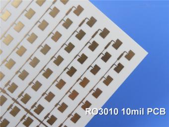
Rogers RO3010 PCB is ideal for a wide range of high-frequency applications, including power amplifiers, filters, couplers, and antennas.
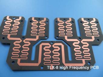
TLX-8 features low dielectric loss, low moisture absorption, and excellent thermal stability, making it ideal for high-frequency and high-speed applications. It has a low dissipation factor, which helps to minimize signal loss and distortion.
 6-11C Shidai Jingyuan, Fuyong, Baoan, Shenzhen, Guangdong, China 518103


For inquiries about our products or pricelist, please leave to us and we will be in touch within 24 hours.
© Copyright: 2026 Shenzhen Bicheng Electronics Technology Co., Ltd.. All Rights Reserved.

IPv6 network supported


