

 Call Us Now !
Tel : +86 755 27374946
Call Us Now !
Tel : +86 755 27374946
 Order Online Now !
Email : info@bichengpcb.com
Order Online Now !
Email : info@bichengpcb.com

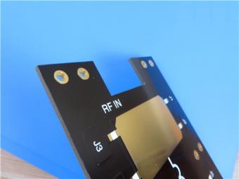
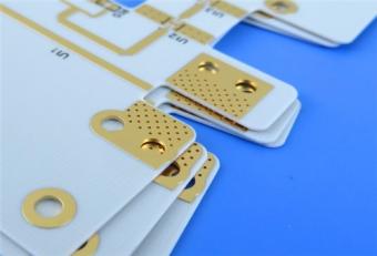
This 31mil RT/duroid 5880 bare copper finished PCB is a specialized low-loss high-frequency circuit solution built on industry-leading PTFE composite substrate. Its zero solder mask, zero silkscreen bare copper design creates clear differentiation from ordinary RF PCBs by minimizing parasitic electrical interference for Ku-band and millimeter-wave transmission systems.
Item NO.:
BIC-581-v666.0Order(MOQ):
1-10Payment:
T/TProduct Origin:
ChinaShipping Port:
ShenzhenLead Time:
7-10 days
31mil Rogers RT/duroid 5880 Double-sided Bare Copper ENIG Finished PCB
1. Product Overview
This article presents a comprehensive technical overview of a precision-engineered 2-layer printed circuit board fabricated on Rogers RT/duroid 5880 high-frequency laminate. Designed for demanding stripline and microstrip applications, this 31mil Rogers board combines exceptional electrical stability with mechanical robustness. With a finished thickness of 0.85 mm (31 mil dielectric core), 1 oz copper cladding, and immersion gold surface finish, it is optimized for low-loss signal transmission up to Ku-band and beyond. The absence of solder mask and silkscreen, coupled with tight dimensional tolerances, makes this RT/duroid 5880 PCB ideal for prototype and production runs in aerospace, defense, and advanced communication systems.
Below, we detail the construction, stackup, and statistical metrics, followed by an in-depth analysis of its performance attributes and a separate technical primer on the RT/duroid 5880 substrate material.
2. Full PCB Construction Parameter Table
This table summarizes all mechanical, surface treatment, processing and testing specifications of the finished PCB.
|
Parameter |
Specification |
|
Base Material |
Rogers RT/duroid® 5880 |
|
Layer Count |
2 |
|
Board Dimensions |
102 mm × 65 mm per panel, tolerance ±0.15 mm |
|
Minimum Trace/Space |
4 mils / 6 mils |
|
Minimum Hole Size (finished) |
0.35 mm |
|
Blind Vias |
No |
|
Finished Board Thickness |
0.85 mm (±0.10 mm typical) |
|
Finished Copper Weight |
1 oz (35 μm / 1.4 mils) |
|
Via Plating Thickness |
20 μm (minimum) |
|
Surface Finish |
Immersion Gold (ENIG) |
|
Top Silkscreen |
No |
|
Bottom Silkscreen |
No |
|
Top Solder Mask |
No |
|
Bottom Solder Mask |
No |
|
Electrical Test |
100% prior to shipment |
3. PCB Layer Stackup Structure Table
This table clearly displays the symmetrical two-layer copper-dielectric stackup thickness distribution of the RT/duroid 5880 high frequency PCB.
|
Layer |
Material |
Thickness |
|
Top Copper (Layer 1) |
Electrodeposited (ED) Cu, 1 oz |
35 μm |
|
Dielectric Core |
RT/duroid® 5880 |
0.787 mm (31 mil) |
|
Bottom Copper (Layer 2) |
Electrodeposited (ED) Cu, 1 oz |
35 μm |
4. PCB Circuit Statistical Parameter Table
This table quantifies all circuit feature counts of the finished PCB to reflect layout complexity and component matching capacity.
|
Metric |
Count |
|
Components |
46 |
|
Total Pads |
53 |
|
Through Hole Pads |
28 |
|
Top SMT Pads |
25 |
|
Bottom SMT Pads |
0 |
|
Vias |
29 |
|
Nets |
2 |
5. Core Manufacturing Differentiated Advantages of This PCB
5.1 Zero coating bare copper design:
Cancel both solder mask and silkscreen layers. Conventional high-frequency PCBs with liquid mask will introduce extra dielectric loss tangent fluctuation; this bare copper scheme maintains the original low-loss electrical property of RT/duroid 5880 substrate, critical for millimeter-wave low insertion loss design.
5.2 Immersion gold surface finish without organic protective film:
Compared with bare copper oxidation risk and HASL uneven tin thickness, ENIG surface keeps consistent solderability for long-term storage while not introducing additional dielectric parasitic parameters.
5.3 31mil standard thick dielectric core matching 1oz copper:
The 0.787mm dielectric thickness provides stable impedance control for 50Ω/75Ωmicrostrip lines under 4/6mil fine line processing, solving impedance deviation issues caused by thin substrate thin copper matching.
5.4 Strict 20μm via plating thickness control:
General PTFE PCB via plating thickness only reaches 10–15μm; 20μm thick plating enhances hole wall conductivity, reduces via insertion loss and avoids via crack under thermal cycling.
5.5 Full electrical testing before shipment:
All vias, pads and signal nets are scanned for continuity, which greatly reduces failure rate of finished RF modules compared with sampling inspection standards.

6. Typical Application Scenarios of This PCB
This double-sided 31mil RT/duroid 5880 PCB is specially developed for high-frequency low-loss circuit systems, covering:
7. Conclusion of PCB Product
This 31mil RT/duroid 5880 bare copper finished PCB is a specialized low-loss high-frequency circuit solution built on industry-leading PTFE composite substrate. Its zero solder mask, zero silkscreen bare copper design creates clear differentiation from ordinary RF PCBs by minimizing parasitic electrical interference for Ku-band and millimeter-wave transmission systems. Standardized 2-layer symmetrical stackup, controlled ultra-fine line width, precise via metallization and full 100% electrical testing deliver consistent, repeatable circuit performance under IPC-Class-2 quality standards.
Supported by RT duroid 5880’s inherent ultra-low Df, stable Dk and low moisture absorption, the product effectively solves core performance bottlenecks of high-frequency antenna and radar modules, serving as a reliable standardized custom PCB option for aerospace, defense and commercial broadband wireless equipment worldwide.
Supplementary Detailed Knowledge of RT/duroid 5880 Copper Clad Laminate (CCL)
1. CCL Material Basic Introduction
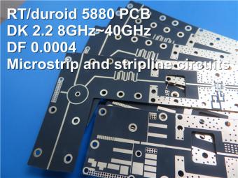
RT/duroid 5880 is a flagship glass microfiber reinforced PTFE copper-clad laminate developed by Rogers Corporation, engineered for stringent microstrip and stripline high-frequency circuit demands. Unlike woven glass fiber-reinforced substrates, randomly distributed ultra-fine glass microfibers inside the PTFE matrix eliminate directional dielectric constant deviation, delivering exceptional Dk uniformity between production panels and across DC to 110GHz wide frequency spectrum. The material features ultra-low dissipation factor that extends stable operation up to Ku-band, Ka-band and W-band millimeter-wave ranges, paired with superior solvent resistance to all etching, plating and cleaning chemicals used in PCB manufacturing.
Standard CCL configurations support electrodeposited copper foil (0.5oz/1oz) and rolled copper foil cladding, with 31mil (0.787mm) being the most widely selected thickness for double-sided small-form-factor RF antenna PCBs. The RT/duroid 5880 laminate achieves UL94 V-0 flame retardant grade and full lead-free reflow compatibility, capable of enduring short-term 260°C peak assembly temperatures without structural or electrical degradation.
2. Complete Datasheet Performance Parameter Table of RT/duroid 5880 CCL
|
Property |
Direction |
Value |
Units |
Condition |
Test Method |
|
Dielectric Constant (εr), Process |
Z |
2.20 ± 0.02 |
— |
10 GHz, 23°C |
IPC-TM-650 2.5.5.5 |
|
Dielectric Constant (εr), Design |
Z |
2.20 (average) |
— |
8–40 GHz |
Differential Phase Length |
|
Dissipation Factor (tan δ) |
Z |
0.0004 – 0.0009 |
— |
1 MHz / 10 GHz |
IPC-TM-650 2.5.5.3 / 2.5.5.5 |
|
Thermal Coefficient of εr |
Z |
–125 |
ppm/°C |
–50 to 150°C |
IPC-TM-650 2.5.5.5 |
|
Volume Resistivity |
Z |
2 × 10⁷ |
Mohm·cm |
C96/35/90 |
ASTM D257 |
|
Surface Resistivity |
Z |
3 × 10⁷ |
Mohm |
C96/35/90 |
ASTM D257 |
|
Specific Heat |
— |
0.96 (0.23) |
J/g·K (cal/g·°C) |
— |
Calculated |
|
Tensile Modulus – at 23°C |
X / Y |
1070 / 860 |
MPa (kpsi) |
A |
ASTM D638 |
|
Tensile Modulus – at 100°C |
X / Y |
450 / 380 |
MPa (kpsi) |
— |
ASTM D638 |
|
Ultimate Tensile Stress (23°C) |
X / Y |
29 / 27 |
MPa (kpsi) |
— |
ASTM D638 |
|
Ultimate Tensile Stress (100°C) |
X / Y |
20 / 18 |
MPa (kpsi) |
— |
ASTM D638 |
|
Ultimate Tensile Strain (23°C) |
X / Y |
6.0 / 4.9 |
% |
— |
ASTM D638 |
|
Compressive Modulus – at 23°C |
X / Y / Z |
710 / 710 / 940 |
MPa (kpsi) |
A |
ASTM D695 |
|
Compressive Modulus – at 100°C |
X / Y / Z |
500 / 500 / 670 |
MPa (kpsi) |
— |
ASTM D695 |
|
Ultimate Compressive Stress (23°C) |
X / Y / Z |
27 / 29 / 52 |
MPa (kpsi) |
— |
ASTM D695 |
|
Ultimate Compressive Stress (100°C) |
X / Y / Z |
22 / 21 / 43 |
MPa (kpsi) |
— |
ASTM D695 |
|
Compressive Strain (23°C) |
X / Y / Z |
8.5 / 7.7 / 12.5 |
% |
— |
ASTM D695 |
|
Compressive Strain (100°C) |
X / Y / Z |
8.4 / 7.8 / 17.6 |
% |
— |
ASTM D695 |
|
Moisture Absorption |
— |
0.02 |
% |
D48/50 (0.062” thick) |
ASTM D570 |
|
Thermal Conductivity |
Z |
0.2 |
W/m·K |
80°C |
ASTM C518 |
|
Coefficient of Thermal Expansion (CTE) |
X / Y / Z |
31 / 48 / 237 |
ppm/°C |
0–100°C |
IPC-TM-650 2.4.41 |
|
Thermal Decomposition Temperature (Td) |
— |
500 |
°C TGA |
— |
ASTM D3850 |
|
Density |
— |
2.2 |
g/cm³ |
— |
ASTM D792 |
|
Copper Peel Strength (1 oz ED foil, after solder float) |
— |
31.2 (5.5) |
pli (N/mm) |
— |
IPC-TM-650 2.4.8 |
|
Flammability |
— |
V 0 |
— |
— |
UL 94 |
|
Lead Free Process Compatible |
— |
Yes |
— |
— |
— |
3. Key Unique Core Features of RT/duroid 5880 CCL
3.1 Lowest electrical loss among reinforced PTFE laminates:
The tanδupper limit only reaches 0.0009 at 10GHz, far lower than FR-4, high Tg hydrocarbon and other microwave substrates, effectively reducing circuit insertion loss for high Q filter and antenna design.
3.2 Ultra-low moisture absorption (0.02%):
Almost no Dk shift under high humidity environment, avoiding antenna gain drift and signal distortion in outdoor communication equipment.
3.3 Isotropic electrical characteristics:
Random glass microfiber eliminates X/Y directional electrical difference, consistent impedance control for arbitrarily routed microstrip lines.
3.4 Broadband stable electrical properties:
Dk remains unchanged across 1MHz to 40GHz, suitable for ultra-wideband transceiving circuits.
3.5 Outstanding chemical resistance:
Inert PTFE matrix will not corrode or swell under acidic, alkaline etching liquid and plating solution, improving PCB mass production yield.
4. Standard CCL Supply Specifications & Optional Customization
4.1 Standard Dielectric Thickness Series
Tolerance controlled within±0.0005”~±0.0030”; extra thickness range 0.0035”–0.375”available on customized order.
4.2 Standard Copper Cladding Options
4.3Standard Panel Blank Sizes
Additional Custom Cladding Choices
Heavy copper foil, resistive copper foil, unclad dielectric sheet, aluminum/brass metal backplane cladding can be specified by customers when ordering.
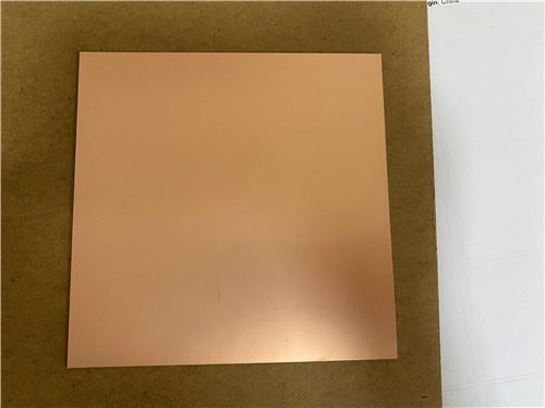
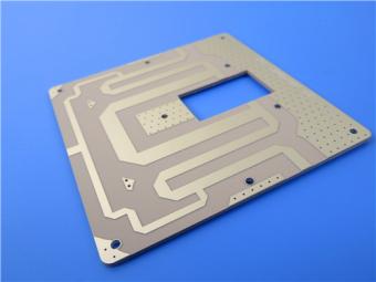
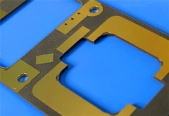
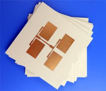
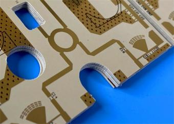
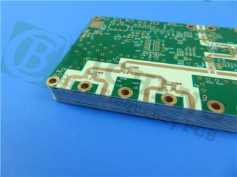
5. CCL Reference Image Description
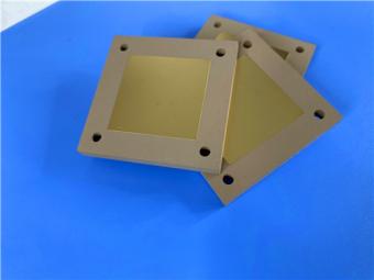
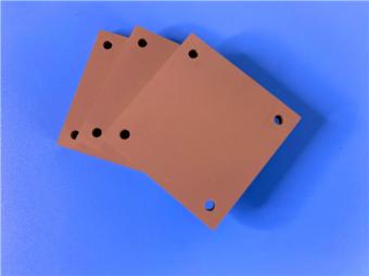
The Rogers 5880 copper clad laminate raw panel presents uniform matte copper surface on both sides, with milky white semi-transparent PTFE dielectric core inside. After cutting and PCB etching, the substrate maintains flatness without warpage; the finished bare copper PCB (no solder mask) shows consistent golden immersion gold traces after surface finishing, with smooth hole walls formed by 20μm thick via plating, fully reflecting the excellent machinability of RT/duroid 5880 CCL.

6. CCL Section Closing Summary
RT/duroid 5880 copper-clad laminate is the foundational high-frequency substrate of the 31mil double-sided bare copper PCB introduced above. Its unique microglass reinforced PTFE formula delivers industry-leading low-loss, isotropic electrical performance and robust environmental stability that cannot be replicated by conventional FR-4 or hydrocarbon ceramic laminates. The complete datasheet parameter table quantifies all electrical, mechanical, thermal and reliability indicators, providing accurate simulation and manufacturing reference for RF circuit designers. Matching with bare copper no-mask PCB design amplifies the material’s inherent low-loss advantages, forming a complete high-performance signal transmission solution for advanced millimeter-wave and microwave electronic equipment.


If you have questions or suggestions,please leave us a message,we will reply you as soon as we can!
Categories
New Products
30mil Taconic CER-10 2-layer Immersion Silver DK10 High Frequency Laminate PCB
31mil Rogers RT/duroid 5880 Double-sided Bare Copper ENIG Finished PCB
Wangling TFA294 Laminate 40mil Immersion Silver No Solder Mask Silkscreen Custom PCB
50mil TMM6 PCB 2-layer EPIG Rogers DK6.0 Substrate No Solder Mask Silkscreen
60mil TMM10 PCB 1-layer OSP Microwave High Frequency Laminate No Solder Mask
Wangling F4BTMS265 Custom PCB 30mil 2-layer ENIG Black Solder Mask White Silkscreen
RO4835 20mil Rogers Laminate 2-layer Immersion Gold Custom PCB
Rogers 20mil DiClad 527 PCB 2-layer Immersion Gold No Solder Mask Black Silkscreen
This is a type of double sided RF PCB built on RT/duroid 5880 for the application of Radar Systems.
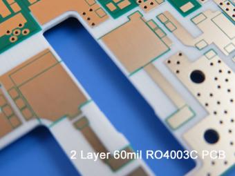
RO4003C PCBs are hydrocarbon ceramic filled laminates, not PTFE which are designed to offer superior high frequency performance.
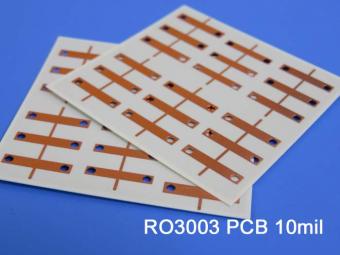
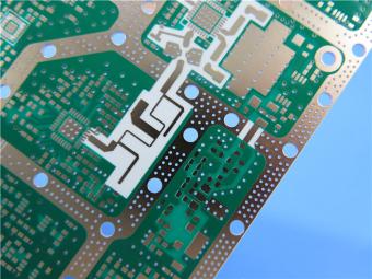
Rogers RO3003 high frequency circuit materials are ceramic-filled PTFE composites intended for use in commercial microwave and RF applications. It was designed to offer exceptional electrical and mechanical stability at competitive prices.
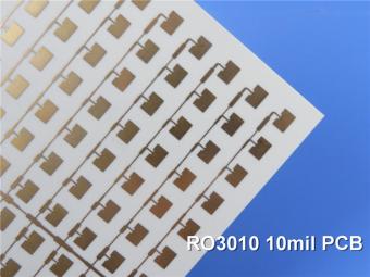
RO3010 laminates are competitively priced products with exceptional mechanical and electrical stability. This stability simplifies the design of broadband components and allows the materials to be used in a wide range of applications over a very broad range of frequencies.
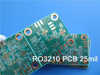
These RO3210 materials are engineered to offer exceptional electrical performance and mechanical stability. RO3210 laminates combine the surface smoothness of a non-woven PTFE laminate.
RT/duroid 6035HTC laminates are an exceptional choice for high power applications.
TC350 is designed to provide enhanced heat-transfer through “Best-In-Class” thermal conductivity, while reducing dielectric loss and insertion loss. Lower losses result in higher Amplifier and Antenna Gains/Efficiencies.
RO3035 materials exhibit a coefficient of thermal expansion(CTE) in the X and Y axis of 17 ppm/℃. This expansion coefficient is matched to that of copper, which allows the material to exhibit excellent dimensional stability.
 6-11C Shidai Jingyuan, Fuyong, Baoan, Shenzhen, Guangdong, China 518103


For inquiries about our products or pricelist, please leave to us and we will be in touch within 24 hours.
© Copyright: 2026 Shenzhen Bicheng Electronics Technology Co., Ltd.. All Rights Reserved.

IPv6 network supported


