

 Call Us Now !
Tel : +86 755 27374946
Call Us Now !
Tel : +86 755 27374946
 Order Online Now !
Email : info@bichengpcb.com
Order Online Now !
Email : info@bichengpcb.com
The F4BTMS series is an upgraded version of the F4BTM series. Building upon its foundation, significant technological advancements have been made in material formulation and manufacturing processes.
Item NO.:
BIC-234-v299.0Order(MOQ):
1-10Payment:
T/TProduct Origin:
ChinaShipping Port:
ShenzhenLead Time:
7-10 daysF4BTMS Series High Frequency PCB 3.2mm Substrate
Introduction
The F4BTMS series Laminate is an upgraded version of the F4BTM series laminate. Building upon its foundation, significant technological advancements have been made in material formulation and manufacturing processes. The F4BTMS material now incorporates a large amount of ceramics and utilizes ultra-thin and ultra-fine fiberglass cloth reinforcement. These enhancements have greatly improved the material's performance, resulting in a wider range of dielectric constants. It is a high-reliability material suitable for aerospace applications, capable of replacing similar foreign products.
By incorporating a small amount of ultra-thin and ultra-fine fiberglass cloth reinforcement, along with a significant and uniform mixture of special nanoceramics and polytetrafluoroethylene resin, the fiberglass effect during the propagation of electromagnetic waves is minimized, reducing dielectric loss and enhancing dimensional stability. The F4BTMS material exhibits reduced anisotropy in the X/Y/Z directions, allowing for higher frequency usage, increased electrical strength, and improved thermal conductivity. The material also possesses excellent low coefficient of thermal expansion and stable dielectric temperature characteristics.
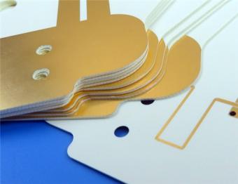
The F4BTMS series PCBcomes standard with RTF low roughness copper foil, which not only reduces conductor loss but also provides excellent peel strength. It can be paired with copper-based or aluminum-based options.
F4BTMS294 can be combined with buried 50Ω resistor copper foil to create a resistor film substrate.
The F4BTMS circuit boards can be processed using standard PTFE board fabrication techniques, taking advantage of the excellent mechanical and physical properties of the material. They are suitable for multi-layer, high-layer-count, and backplane processing. Additionally, they exhibit excellent processability in dense hole and fine line routing.
Product Features
-Minimal dielectric constant tolerance and excellent batch-to-batch consistency.
-Extremely low dielectric loss.
-Stable dielectric constant and low loss within frequencies up to 40GHz, meeting the requirements of phase-sensitive applications.
-Excellent temperature coefficient of dielectric constant and dielectric loss, maintaining frequency and phase stability between -55°C and 150°C.
-Excellent resistance to radiation, retaining stable dielectric and physical properties even after exposure to irradiation.
-Low outgassing performance, meeting the vacuum outgassing requirements for aerospace applications.
-Minimal thermal expansion coefficients in the X/Y/Z directions, ensuring dimensional stability and reliable hole copper connections.
-Improved thermal conductivity, suitable for high-power applications.
-Excellent dimensional stability.
-Low water absorption.
Models & Data Sheet
| Product Technical Parameters | Product Models & Data Sheet | ||||||||||||
| Product Features | Test Conditions | Unit | F4BTMS220 | F4BTMS233 | F4BTMS255 | F4BTMS265 | F4BTMS294 | F4BTMS300 | F4BTMS350 | F4BTMS430 | F4BTMS450 | F4BTMS615 | F4BTMS1000 |
| Dielectric Constant (Typical) | 10GHz | / | 2.2 | 2.33 | 2.55 | 2.65 | 2.94 | 3.00 | 3.50 | 4.30 | 4.50 | 6.15 | 10.20 |
| Dielectric Constant Tolerance | / | / | ±0.02 | ±0.03 | ±0.04 | ±0.04 | ±0.04 | ±0.04 | ±0.05 | ±0.09 | ±0.09 | ±0.12 | ±0.2 |
| Dielectric Constant (Design) | 10GHz | / | 2.2 | 2.33 | 2.55 | 2.65 | 2.94 | 3.0 | 3.50 | 4.3 | 4.5 | 6.15 | 10.2 |
| Loss Tangent (Typical) | 10GHz | / | 0.0009 | 0.0010 | 0.0012 | 0.0012 | 0.0012 | 0.0013 | 0.0016 | 0.0015 | 0.0015 | 0.0020 | 0.0020 |
| 20GHz | / | 0.0010 | 0.0011 | 0.0013 | 0.0014 | 0.0014 | 0.0015 | 0.0019 | 0.0019 | 0.0019 | 0.0023 | 0.0023 | |
| 40GHz | / | 0.0013 | 0.0015 | 0.0016 | 0.0018 | 0.0018 | 0.0019 | 0.0024 | 0.0024 | 0.0024 | / | / | |
| Dielectric Constant Temperature Coefficient | -55 º~150ºC | PPM/℃ | -130 | -122 | -92 | -88 | -20 | -20 | -39 | -60 | -58 | -96 | -320 |
| Peel Strength | 1 OZ RTF copper | N/mm | >2.4 | >2.4 | >1.8 | >1.8 | >1.2 | >1.2 | >1.2 | >1.2 | >1.2 | >1.2 | >1.2 |
| Volume Resistivity | Standard Condition | MΩ.cm | ≥1×10^8 | ≥1×10^8 | ≥1×10^8 | ≥1×10^8 | ≥1×10^8 | ≥1×10^8 | ≥1×10^8 | ≥1×10^8 | ≥1×10^8 | ≥1×10^8 | ≥1×10^8 |
| Surface Resistivity | Standard Condition | MΩ | ≥1×10^8 | ≥1×10^8 | ≥1×10^8 | ≥1×10^8 | ≥1×10^8 | ≥1×10^8 | ≥1×10^8 | ≥1×10^8 | ≥1×10^8 | ≥1×10^8 | ≥1×10^8 |
| Electrical Strength (Z direction) | 5KW,500V/s | KV/mm | >26 | >30 | >32 | >34 | >40 | >40 | >42 | >44 | >45 | >48 | >23 |
| Breakdown Voltage (XY direction) | 5KW,500V/s | KV | >35 | >38 | >40 | >42 | >48 | >52 | >55 | >52 | >54 | >55 | >42 |
| Coefficientof Thermal Expansion (X, Y direction) | -55 º~288ºC | ppm/ºC | 40, 50 | 35, 40 | 15, 20 | 15, 20 | 10, 12 | 10, 11 | 10, 12 | 13, 12 | 12, 12 | 10, 12 | 16, 18 |
| Coefficientof Thermal Expansion (Z direction) | -55 º~288ºC | ppm/ºC | 290 | 220 | 80 | 72 | 22 | 22 | 20 | 47 | 45 | 40 | 32 |
| Thermal Stress | 260℃, 10s,3 times | / | No delamination | No delamination | No delamination | No delamination | No delamination | No delamination | No delamination | No delamination | No delamination | No delamination | No delamination |
| Water Absorption | 20±2℃, 24 hours | % | 0.02 | 0.02 | 0.025 | 0.025 | 0.02 | 0.025 | 0.03 | 0.08 | 0.08 | 0.1 | 0.03 |
| Density | Room Temperature | g/cm3 | 2.18 | 2.22 | 2.26 | 2.26 | 2.25 | 2.28 | 2.3 | 2.51 | 2.53 | 2.75 | 3.2 |
| Long-Term Operating Temperature | High-Low Temperature Chamber | ℃ | -55~+260 | -55~+260 | -55~+260 | -55~+260 | -55~+260 | -55~+260 | -55~+260 | -55~+260 | -55~+260 | -55~+260 | -55~+260 |
| Thermal Conductivity | Z direction | W/(M.K) | 0.26 | 0.28 | 0.31 | 0.36 | 0.58 | 0.58 | 0.6 | 0.63 | 0.64 | 0.67 | 0.81 |
| Flammability | / | UL-94 | V-0 | V-0 | V-0 | V-0 | V-0 | V-0 | V-0 | V-0 | V-0 | V-0 | V-0 |
| Material Composition | / | / | PTFE,Ultra-thin and ultra-fine (quartz) fiberglass. | PTFE,Ultra-thin and ultra-fine fiberglass, ceramics. | |||||||||
Our PCB Capability (F4BTMS)
| PCB Capability (F4BTMS) | |||
| PCB Material: | PTFE,Ultra-thin and ultra-fine fiberglass, ceramics. | ||
| Designation (F4BTMS ) | F4BTMS | DK (10GHz) | DF (10 GHz) |
| F4BTMS220 | 2.2±0.02 | 0.0009 | |
| F4BTMS233 | 2.33±0.03 | 0.0010 | |
| F4BTMS255 | 2.55±0.04 | 0.0012 | |
| F4BTMS265 | 2.65±0.04 | 0.0012 | |
| F4BTMS294 | 2.94±0.04 | 0.0012 | |
| F4BTMS300 | 3.0±0.04 | 0.0013 | |
| F4BTMS350 | 3.5±0.05 | 0.0016 | |
| F4BTMS430 | 4.3±0.09 | 0.0015 | |
| F4BTMS450 | 4.5±0.09 | 0.0015 | |
| F4BTMS615 | 6.15±0.12 | 0.0020 | |
| F4BTMS1000 | 10.2±0.2 | 0.0020 | |
| Layer count: | Single Sided, Double Sided PCB, Multilayer PCB, Hybrid PCB | ||
| Copper weight: | 0.5oz (17 µm), 1oz (35µm), 2oz (70µm) | ||
| Dielectric thickness | 0.09mm (3.5mil), 0.127mm (5mil), 0.254mm(10mil),0.508mm(20mil), 0.635mm(25mil), 0.762mm(30mil), 0.787mm(31mil), 1.016mm(40mil), 1.27mm(50mil), 1.5mm(59mil), 1.524mm(60mil), 1.575mm(62mil), 2.03mm(80mil), 2.54mm(100mil), 3.175mm(125mil), 4.6mm(160mil), 5.08mm(200mil), 6.35mm(250mil) | ||
| PCB size: | ≤400mm X 500mm | ||
| Solder mask: | Green, Black, Blue, Yellow, Red etc. | ||
| Surface finish: | Bare copper, HASL, ENIG, Immersion silver, Immersion tin, OSP, Pure gold, ENEPIG etc.. | ||
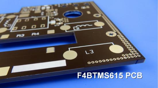
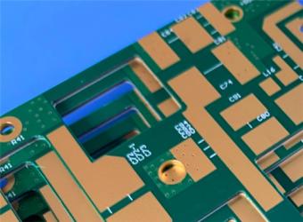
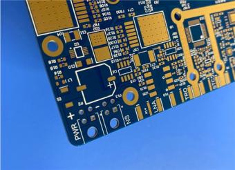
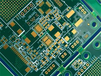
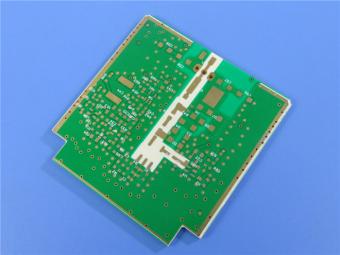
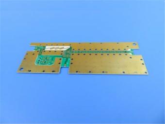
A F4BTMS PCB and Typical Applications:
Presented on the screen is an F4BTMS high-frequency PCB, utilizing a 3.2mm substrate with HASL coating on the pads. F4BTMS PCBs are extensively employed in various domains, including:

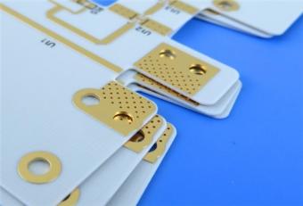
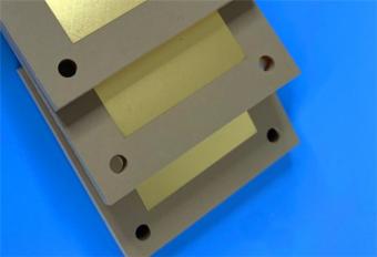
Final (F4BTMS series aluminum-based/copper-based boards)
This series oflaminates can provide aluminum-based or copper-based materials, where one side of the dielectric layer is covered with copper foil, and the other side is covered with an aluminum-based or copper-based layer. This configuration serves as shielding or heat dissipation.
The model numbers are F4BTMS***-AL or F4BTMS***-CU. For example,
F4BTMS220-AL represents F4BTMS220 with aluminum-based substrate.
F4BTMS294-CU represents F4BTMS294 with copper-based substrate.


Previous:
6-Layer Rigid-Flex Circuits 1.0mm Thick Multilayer S1000-2M R-F777 Polyimide PCBNext:
F4BTME Dielectric Layer High Frequency PCB DK 3.5 F4BTME 1.524mm SubstrateIf you have questions or suggestions,please leave us a message,we will reply you as soon as we can!
Categories
New Products
RO4835 20mil Rogers Laminate 2-layer Immersion Gold Custom PCB
Rogers 20mil DiClad 527 PCB 2-layer Immersion Gold No Solder Mask Black Silkscreen
Wangling WL-CT300 5mil Laminate Pure Gold Plating High Frequency PCB
Wangling TF300 25mil DK3.0 Laminate 2-layer PCB Immersion Gold Black Silkscreen
2-Layer 0.5mm TP440 PCB Wangling TP DK4.4 Laminate Immersion Gold
20-Layer Panasonic TU872 HDI PCB ENEPIG 3.0mm Finished Thick Laser-drilled Blind Vias
10-Layer Rogers RO4003C + 370HR FR4 Hybrid Laminate PCB ENIG Impedance Control
8-Layer 10oz Heavy Copper TU-865 Substrate PCB With ENIG Blind &Buried Via

RF-10 25mil Taconic PCB Materials stands out as a high-performance solution for RF applications. Its exceptional electrical properties, dimensional stability, thermal conductivity, and adhesion characteristics make it an ideal choice for demanding applications.
The PCB has a 4-layer hybrid stackup with a 0.5oz+plating ground layer, two 1oz ground layers, and a 0.5oz+plating signal layer.
The dimensions of the board are 55.00 x 26.00 mm, with a tolerance of +/- 0.15mm. The board has 16 components, 26 total pads, 9 through-hole pads, 10 top SMT pads, 7 bottom SMT pads, 77 vias, and 82 nets.
Rogers RO4003C PCB is an innovative and advanced circuit board that is made with high-quality materials.
The RO4350B PCB offers a range of benefits that make it an ideal choice for high-frequency applications. Its low dielectric loss and high thermal conductivity make it perfect for high-frequency applications such as RF and microwave circuits.
Bicheng PCB Ships High-Quality PCBs with Shengyi Tg150 ℃ S1000H Material and Advanced Stackup
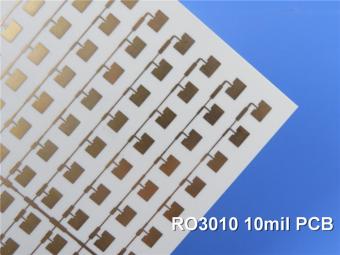
Rogers RO3010 PCB is ideal for a wide range of high-frequency applications, including power amplifiers, filters, couplers, and antennas.
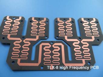
TLX-8 features low dielectric loss, low moisture absorption, and excellent thermal stability, making it ideal for high-frequency and high-speed applications. It has a low dissipation factor, which helps to minimize signal loss and distortion.
 6-11C Shidai Jingyuan, Fuyong, Baoan, Shenzhen, Guangdong, China 518103


For inquiries about our products or pricelist, please leave to us and we will be in touch within 24 hours.
© Copyright: 2026 Shenzhen Bicheng Electronics Technology Co., Ltd.. All Rights Reserved.

IPv6 network supported


