
 Call Us Now !
Tel : +86 755 27374946
 Order Online Now !
Email : info@bichengpcb.com
RF-10 high frequency materials are engineered to
provide a cost effective substrates, responding to a need in RF applications
for size reduction.
Item NO.:
BIC-181-v115.0Order(MOQ):
1-10Payment:
T/TProduct Origin:
ChinaColor:
WhiteShipping Port:
ShenzhenLead Time:
7-10 days
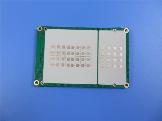
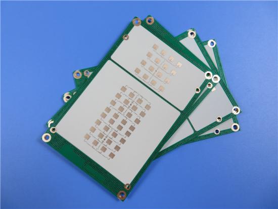
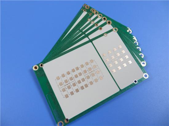
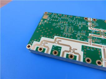
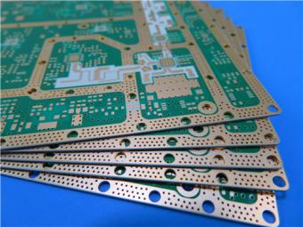
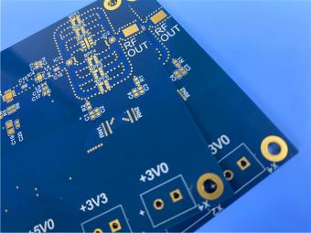
RF-10 Printed Circuit Board 10mil 20mil 60mil Taconic RF-10 High Frequency PCB Low Loss High DK RF PCB
(Printed Circuit Boards are custom-made products, the picture and parameters shown are just for reference)
General Description
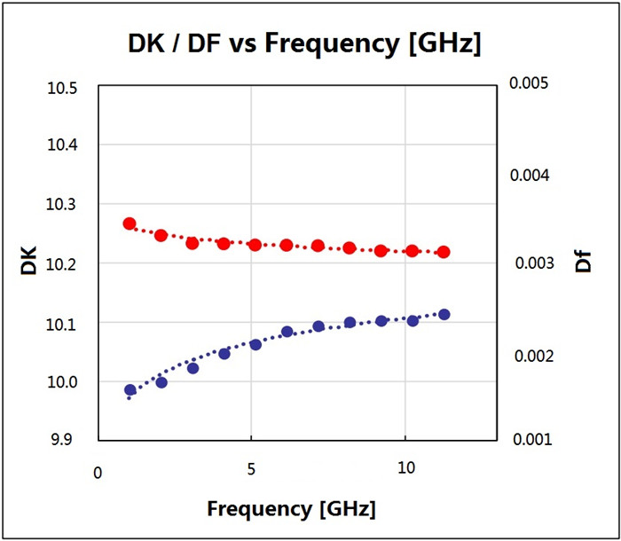
Taconic's RF-10 laminates are composites of ceramic filled PTFE and woven fiberglass, which have the advantage of high dielectric constant (10.2 10GHz) and low dissipation factor (0.0025 10GHz). Thin woven fiberglass reinforcement is used to offer both low dielectric loss and improved rigidity for ease of handling and improved dimensional stability for multilayer circuits.
RF-10 bonds well to smooth low profile copper too. The low dissipation combined with the use of very smooth copper results in optimal insertion losses at higher frequency where skin effect losses play a substantial role.
Features Benefits
1.Excellent adhesion to smooth coppers
2.Excellent dimensional stability
3.Excellent price/performance ratio
4.High thermal conductivity for enhanced thermal management
5.High DK for RF circuit size reduction
6.Low 0.0025 loss tangent @ 10 GHz
7.Low X, Y, Z expansion
8.Tight DK tolerance (10.2 +/-0.3)
Typical Applications
1.Aircraft Collision Avoidance Systems
2.GPS Antennas
3.Microstrip Patch Antennas
4.Passive Components (filters, couplers, power dividers)
5.Satellite Components
Our PCB Capability (RF-10)
| PCB Capability (RF-10) | |
| PCB Material: | Composites of Ceramic Filled PTFE and Woven Fiberglass |
| Designation: | RF-10 |
| Dielectric constant: | 10.2 |
| Dissipation Factor | 0.0025 10GHz |
| Layer count: | Double Sided PCB, Multilayer PCB, Hybrid PCB |
| Copper weight: | 0.5oz (17 µm), 1oz (35µm), 2oz (70µm) |
| PCB thickness: | 10mil (0.254mm), 20mil (0.508mm), 25mil (0.635mm), 60mil (1.524mm ), 125mil ( 3.175mm ) |
| PCB size: | ≤400mm X 500mm |
| Solder mask: | Green, Black, Blue, Yellow, Red etc. |
| Surface finish: | Bare copper, HASL, ENIG, Immersion silver, Immersion tin, OSP etc.. |
RF-10 Typical Values
| RF-10 Typical Values | |||||
| Property | Test Method | Unit | Value | Unit | Value |
| Dk @ 10 GHz | IPC-650 2.5.5.5.1 Mod. | 10.2±0.3 | 10.2±0.3 | ||
| Df @ 10 GHz | IPC-650 2.5.5.5.1 Mod. | 0.0025 | 0.0025 | ||
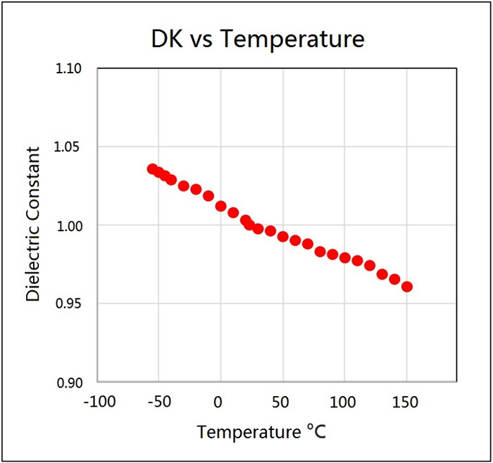
| TcK†(-55 to 150 °C) | IPC-650 2.5.5.6 | ppm/°C | -370 | ppm/°C | -370 |
| Moisture Absorption | IPC-650 2.6.2.1 | % | 0.08 | % | 0.08 |
| Peel Strength(1 oz. RT copper) | IPC-650 2.4.8 (solder) | lbs/in | 10 | N/mm | 1.7 |
| Volume Resistivity | IPC-650 2.5.17.1 | Mohm/cm | 6.0 x 10⁷ | Mohm/cm | 6.0 x 10⁷ |
| Surface Resistivity | IPC-650 2.5.17.1 | Mohm | 1.0 x 10⁸ | Mohm | 1.0 x 10⁸ |
| Flexural Strength(MD) | IPC - 650 - 2.4.4 | psi | 14,000 | N/mm2 | 96.53 |
| Flexural Strength(CD) | IPC - 650 - 2.4.4 | psi | 10,000 | N/mm2 | 68.95 |
| Tensile Strength(MD) | IPC - 650 - 2.4.19 | psi | 8,900 | N/mm2 | 62.57 |
| Tensile Strength(CD) | IPC - 650 - 2.4.19 | psi | 5,300 | N/mm2 | 37.26 |
| Dimensional Stability | IPC-650 2.4.39(After Etch) | % (25 mil-MD) | -0.0032 | % (25 mil-CD) | -0.0239 |
| Dimensional Stability | IPC-650 2.4.39(After Bake) | % (25 mil-MD) | -0.0215 | % (25 mil-CD) | -0.0529 |
| Dimensional Stability | IPC-650 2.4.39(After Stress) | % (25 mil-MD) | -0.0301 | % (25 mil-CD) | -0.0653 |
| Dimensional Stability | IPC-650 2.4.39(After Etch) | % (60 mil-MD) | -0.0027 | % (60 mil-CD) | -0.0142 |
| Dimensional Stability | IPC-650 2.4.39(After Bake) | % (60 mil-MD) | -0.1500 | % (60 mil-CD) | -0.0326 |
| Dimensional Stability | IPC-650 2.4.39(After Stress) | % (60 mil-MD) | -0.0167 | % (60 mil-CD) | -0.0377 |
| Density(Specific Gravity) | IPC-650-2.3.5 | g/cm3 | 2.77 | g/cm3 | 2.77 |
| Specific Heat | IPC-650-2.4.50 | J/g°C | 0.9 | J/g°C | 0.9 |
| Thermal Conductivity(Unclad) | IPC-650-2.4.50 | W/M*K | 0.85 | W/M*K | 0.85 |
| CTE (X -Y axis)(50 to 150 °C) | IPC-650 2.4.41 | ppm/°C | 16-20 | ppm/°C | 16-20 |
| CTE (Z axis)(50 to 150 °C) | IPC-650 2.4.41 | ppm/°C | 25 | ppm/°C | 25 |
| Flammability Rating | Internal | V-0 | V-0 | ||
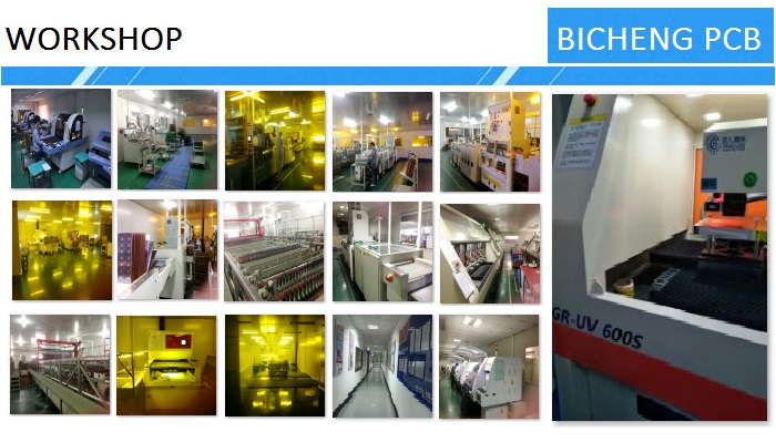
BICHNEG PCB WORKSHOP:
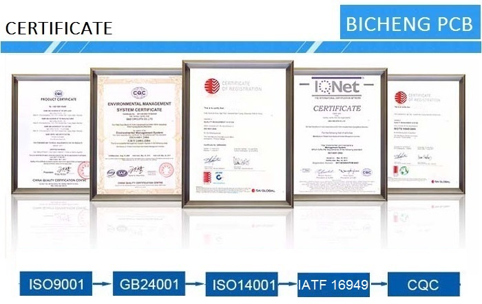
BICHNEG PCB CERTIFICATION:
BICHENG PCB MAIN COURIERS:
Previous:
TRF-45 High Frequency PCB Taconic High Thermal Conductivity Circuit BoardNext:
Taconic High Frequency PCB Built on TLX-9 62mil 1.575mm With Immersion SilverIf you have questions or suggestions,please leave us a message,we will reply you as soon as we can!
Categories
New Products
10-Layer RO4350B + TU-768 Hybrid PCB with Via Copper Capped ENIG Surface Finish
8-Layer 6.6mil Rogers RO4350B + Isola I-Tera MT40 Hybrid PCB 1.636mm Pressed Thickness ENEPIG
6-Layer 5mil Rogers RO3003 Mixed-Laminated with Isola 370HR 0.82 mm Hybrid PCB with ENIG
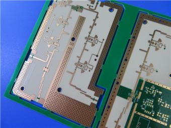
4-Layer 8mil RO4003C + Tg170 FR-4 Hybrid PCB with ENIG — 0.556mm Thin Build
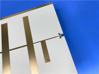
1100 × 350mm Long-Format Rogers RO4003C 32 mil core Double-Sided High-Frequency PCB
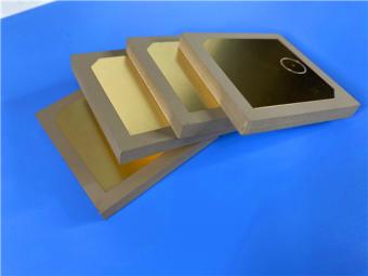
Wangling TP2200 PCB 0.8mm Substrate Immersion Gold 2-Layer High-Dk (Dk 22) RF Board
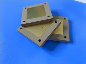
Rogers TMM10 PCB 5.08mm Core ENIG 2-Layer High-Dk Microwave Board
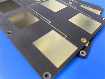
Taconic TLX-8 PCB 50mil ENIG 2-Layer High-Frequency RF Circuit Board
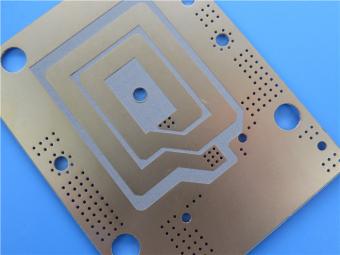
RF-35TC is a type of high frequency material from Taconic company. It offers a "best in class" low dissipation factor with high thermal conductivity.
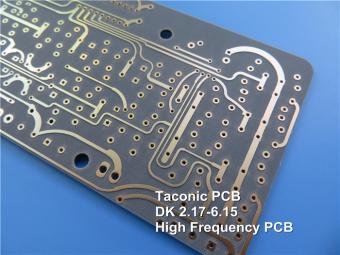
TLX offers reliability in a wide range of RF applications. This material is versatile due to its 2.45 - 2.65 DK range and available thicknesses and copper cladding. It is suitable for low layer count microwave designs.
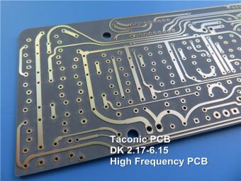
TLF-35A is another type of low cost RF material. It's the best choice for low cost, high volume commercial microwave and radio frequency applications.
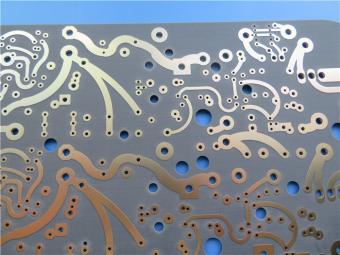
CER-10 is an organic-ceramic DK-10 laminate in the ORCER family of Taconic products. It is based on a woven glass reinforcement. CER-10 exhibits exceptional interlaminar bond strength and solder resistance.
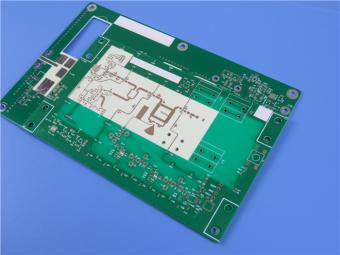
RO4360G2 laminates of Rogers Corporation are 6.15 Dk, low loss, glass-reinforced, hydrocarbon ceramic-filled thermoset materials that provide the ideal balance of performance and processing ease.
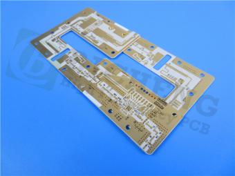
RF-60A is an organic-ceramic laminate in the ORganic CERamic(ORCER) family of Taconic products.
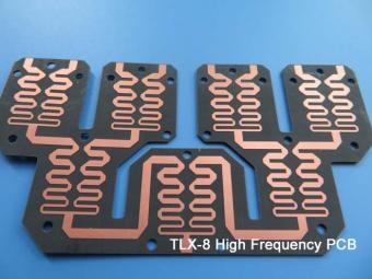
TLX is PTFE based fiberglass laminate, it is ideal for use in radar systems, mobile communications, microwave test equipment, microwave transmission devices and RF components.
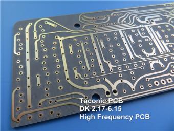
TLX offers reliability in a wide range of RF applications. This material is versatile due to its 2.45 - 2.65 DK range and available thicknesses and copper cladding. It is suitable for low layer count microwave designs
 6-11C Shidai Jingyuan, Fuyong, Baoan, Shenzhen, Guangdong, China 518103


For inquiries about our products or pricelist, please leave to us and we will be in touch within 24 hours.
© Copyright: 2026 Shenzhen Bicheng Electronics Technology Co., Ltd.. All Rights Reserved.

IPv6 network supported


