

 Call Us Now !
Tel : +86 755 27374946
Call Us Now !
Tel : +86 755 27374946
 Order Online Now !
Email : info@bichengpcb.com
Order Online Now !
Email : info@bichengpcb.com
RO4725JXR RF PCBs offer a range of advantages due to their unique properties
Item NO.:
BIC-216-v236.0Order(MOQ):
1-10Payment:
T/TProduct Origin:
ChinaShipping Port:
ShenzhenLead Time:
7-10 days
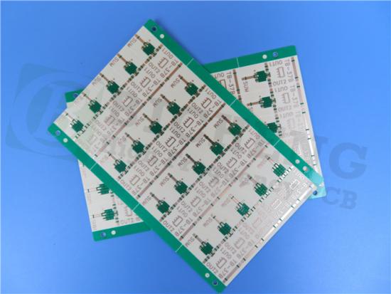
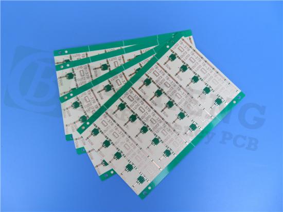
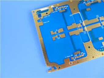
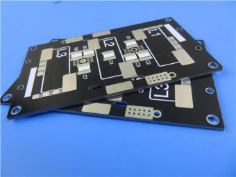
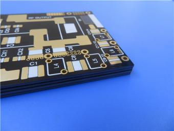
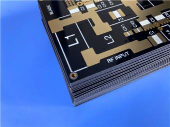
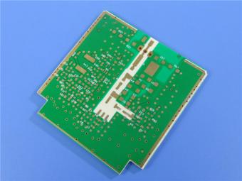
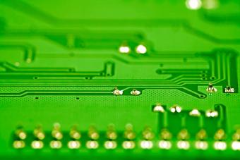
RO4725JXR Antenna PCB Built on 30.7mil 0.78mm Substrates with Double Layer Copper and Immersion Golds
(Printed Circuit Boards are custom-made products, the picture and parameters shown are just for reference)
Brief Introduction
This 2-layer rigid PCB features a stackup with copper_layer_1 of 35 μm, a Rogers RO4725JXR Core of 30.7mil (0.780 mm), and copper_layer_2 of 35 μm. It has a finished board thickness of 0.9mm and a finished Cu weight of 1oz (1.4 mils) on the outer layers. The construction details include board dimensions of 146.15mm x 60.8mm, minimum trace/space of 5/6 mils, and a minimum hole size of 0.5mm. It does not have blind vias and has a via plating thickness of 20 μm.
The RO4725JXR 30.7mil PCB utilizes immersion gold as the surface finish, with green top solder mask and no bottom solder mask. It does not have top or bottom silkscreen. Prior to shipment, a 100% electrical test is performed to ensure quality. The supplied artwork is in the form of Gerber RS-274-X files, and the PCB conforms to IPC-Class-2 quality standard. It is available worldwide.

With a total of 54 components and 67 pads, this PCB has 67 top SMT pads, no bottom SMT pads, 249 vias, and 3 nets. It is commonly used in applications such as Cellular Base Station Antennas and Power Amplifiers.
| Parameters | Values |
| PCB Type | 2-layer rigid PCB |
| Copper_layer_1 | 35 μm |
| Rogers RO4725JXR Core | 30.7mil (0.780 mm) |
| Copper_layer_2 | 35 μm |
| Board Dimensions | 146.15mm x 60.8mm = 20PCS, +/- 0.15mm |
| Minimum Trace/Space | 5/6 mils |
| Minimum Hole Size | 0.5mm |
| Blind vias | No |
| Finished Board Thickness | 0.9mm |
| Finished Cu Weight | 1oz (1.4 mils) outer layers |
| Via Plating Thickness | 20 μm |
| Surface Finish | Immersion Gold |
| Top Silkscreen | No |
| Bottom Silkscreen | No |
| Top Solder Mask | Green |
| Bottom Solder Mask | No |
| Electrical Test | 100% prior to shipment |
| Components | 54 |
| Total Pads | 67 |
| Thru Hole Pads | 0 |
| Top SMT Pads | 67 |
| Bottom SMT Pads | 0 |
| Vias | 249 |
| Nets | 3 |
| Type of Artwork Supplied | Gerber RS-274-X |
| Quality Standard | IPC-Class-2 |
| Availability | Worldwide |
| Typical Applications | Cellular Base Station Antennas and Power Amplifiers |
Features/Benefits:
RO4725JXR RF PCBs offer a range of advantages due to their unique properties:
Reduced PIM:These PCBs exhibit reduced passive inter-modulation, resulting in improved signal quality and reduced interference.
Low insertion loss: With low loss dielectric and low profile foil, these PCBs minimize signal loss during transmission.
RO4725JXR Dk 2.55:The dielectric constant of 2.55 ensures consistent electrical performance and compatibility with standard PTFE-based materials.
The PCBs also feature unique filler and closed microspheres, providing additional benefits:
Low density: With a density of only 1.27 gm/cm3, these PCBs are approximately 30% lighter than PTFE/Glass boards, offering weight savings in applications.
Low Z-axis CTE (Coefficient of Thermal Expansion) of 25.6ppm/°C: This property ensures dimensional stability and reliable performance across temperature variations.
Other notable features include:
High Tg (>280°C):The high glass transition temperature allows for design flexibility and compatibility with automated assembly processes.
Low TCDk (+34 ppm/°C):The low thermal coefficient of dielectric constant ensures consistent circuit performance, minimizing variations due to temperature changes.
Specially formulated thermoset resin system/filler:This formulation offers ease of fabrication and compatibility with plated through-hole (PTH) processes.
In addition, RO4725JXR laminates are environmentally friendly:
Lead-free process compatibility:These PCBs are suitable for lead-free soldering processes.
RoHS compliant:They meet the requirements of the Restriction of Hazardous Substances (RoHS) directive.
Typical applications for RO4725JXR high frequency PCBs include Cellular Base Station Antennas etc.

| Factory Process Capability (2023) | |
| Substrate Types and Brands | Standard FR-4, High Tg FR-4, High Frequency Materials, Polyimide/PET flexible Materials |
| Shengyi, ITEQ, Isola, Taiwan Union, Rogers Corp. Taconic, Panasonic | |
| Board Types | Rigid PCB, Flexible Circuits, Rigid-Flex PCB, Hybrid PCB, HDI PCB |
| CCL Model | High Tg FR-4: S1000-2M, TU-872 SLK, TU-768, IT-180A High CTI FR-4: S1600L, ST115 |
| Rogers Corp: RO4350B, RO4003C, RO4730G3, RO4360G2, RO4533, RO4534, RO4535, RO4835, RO3003, RO3006, RO3010, RO3035, RO3203, RO3210; RT/Duriod 5880; RT/Duriod 5870, RT/Duriod 6002, RT/Duroid 6010, RT/duroid 6035HTC; RT/duroid 5880LZ; TMM3, TMM4, TMM6, TMM10, TMM10i, TMM13i, Kappa 438; AD250C, AD255C, AD300D, AD350A, AD450, AD600, AD1000, TC350; TC600; DiClad 880, DiClad 870, DiClad 527; IsoClad 917 | |
| Taconic: TLF-35; RF-35TC, RF-60A, RF-60TC, RF-35A2, RF-45, RF-10, TRF-45; TLX-0, TLX-6, TLX-7, TLX-8; TLX-9, TLY-3, TLY-5, TLY-5Z; | |
| F4B PTFE Composites: (DK2.2 DK2.65 DK2.85 DK2.94, DK3.0, DK3.2, DK3.38, DK3.5, DK4.0, DK4.4, DK6.15, DK10.2) | |
| Maximum Delivery Size | 1200mm x 572 mm |
| Minimum Finished Board Thickness | L≤2L: 0.15mm; 4L: 0.4mm |
| Maximum Finished Board Thickness | 10.0 mm |
| Blind Buried Holes (Non-crossing) | 0.1mm |
| Maximum Hole Aspect Ratio | 15:01 |
| Minimum Mechanical Drill Hole Diameter | 0.1 mm |
| Through-hole Tolerance | +/- 0.0762 mm |
| Press-fit Hole Tolerance | +/- 0.05mm |
| Non-plated Copper Hole Tolerance | +/- 0.05mm |
| Maximum Number of Layers | 32 |
| Internal and External Layer Maximum Copper Thickness | 12Oz |
| Minimum Drill Hole Tolerance | +/- 2mil |
| Minimum Layer-to-Layer Tolerance | +/- 3mil |
| Minimum Line Width/Spacing | 3mil/3mil |
| Minimum BGA Diameter | 8mil |
| Impedance Tolerance | < 50Ω ±5Ω; ≥50Ω±10% |
| Surface Treatment Processes | Leaded/Lead-free HASL, Immersion Gold, Immersion Silver, Immersion Tin, OSP, ENIG, ENEPIG, Carbon Ink, Peelable Mask, Gold Finger, etc. |


Previous:
Rogers RO3206 High Frequency PCB DK 6.15 RF Circuits 25mil 50mil 0.635mm 1.27mmNext:
Rogers RO4725JXR Antenna Grade High Frequency Printed Circuit Board DK 2.55 RF PCB 30.7mil 60.7milIf you have questions or suggestions,please leave us a message,we will reply you as soon as we can!
Categories
New Products
Wangling 5mil 0.127mm TFA300 Core 2-layer Immersion Gold Green Solder Mask PCB
7.5mil AGC Taconic TLY-5 Substrate Custom PCB EPIG Finish Bare Copper
10mil Rogers CuClad 250 Immersion Gold 2-Layer Rigid Microwave PCB
20mil F4BTMS450 Wangling DK4.5 Laminate Custom PCB HASL LF Finsh
F4BME275 Wangling DK2.75 Laminate 2-Layer 1.6mm Pure Gold RF Custom PCB
Wangling F4BTD350S High Frequency PCB 2-layer 20mil Thick ENIG DK3.5 Substrate

12-layer TG200 TU-872 SLK High-Speed FR4 1.68mm PCB with ENIG Impedance Control

12-Layer RO4350B + RO3010 3.14mm Hybrid PCB Nickel-Free EPIG Surface Finish Blind Via

RF-10 25mil Taconic PCB Materials stands out as a high-performance solution for RF applications. Its exceptional electrical properties, dimensional stability, thermal conductivity, and adhesion characteristics make it an ideal choice for demanding applications.
The PCB has a 4-layer hybrid stackup with a 0.5oz+plating ground layer, two 1oz ground layers, and a 0.5oz+plating signal layer.
The dimensions of the board are 55.00 x 26.00 mm, with a tolerance of +/- 0.15mm. The board has 16 components, 26 total pads, 9 through-hole pads, 10 top SMT pads, 7 bottom SMT pads, 77 vias, and 82 nets.
Rogers RO4003C PCB is an innovative and advanced circuit board that is made with high-quality materials.
The RO4350B PCB offers a range of benefits that make it an ideal choice for high-frequency applications. Its low dielectric loss and high thermal conductivity make it perfect for high-frequency applications such as RF and microwave circuits.
Bicheng PCB Ships High-Quality PCBs with Shengyi Tg150 ℃ S1000H Material and Advanced Stackup
Rogers RO3010 PCB is ideal for a wide range of high-frequency applications, including power amplifiers, filters, couplers, and antennas.
TLX-8 features low dielectric loss, low moisture absorption, and excellent thermal stability, making it ideal for high-frequency and high-speed applications. It has a low dissipation factor, which helps to minimize signal loss and distortion.
 6-11C Shidai Jingyuan, Fuyong, Baoan, Shenzhen, Guangdong, China 518103


For inquiries about our products or pricelist, please leave to us and we will be in touch within 24 hours.
© Copyright: 2026 Shenzhen Bicheng Electronics Technology Co., Ltd.. All Rights Reserved.

IPv6 network supported


