

 Call Us Now !
Tel : +86 755 27374946
Call Us Now !
Tel : +86 755 27374946
 Order Online Now !
Email : info@bichengpcb.com
Order Online Now !
Email : info@bichengpcb.com
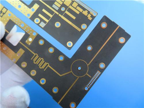
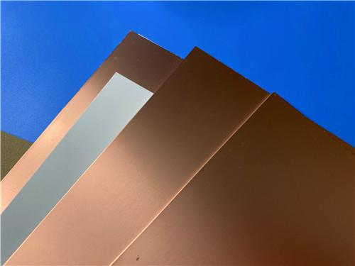
F4BTMS220 is a PTFE-based copper-clad laminate for aerospace and microwave use. It combines PTFE resin with a high loading of uniformly distributed nano-ceramics and only a little ultra-thin, ultra-fine quartz glass cloth.
Item NO.:
BIC-629-v714Order(MOQ):
1-10Payment:
T/TProduct Origin:
ChinaShipping Port:
ShenzhenLead Time:
7-10 days
Wangling F4BTMS220 2-Layer DK2.2 PCB 10 mil Core with Immersion Gold
A high-frequency PTFE / ceramic RF board for microwave, radar and phased-array applications
Overview
This article presents a production-ready two-layer rigid PCB on Wangling F4BTMS220, a low-Dk, ultra-low-loss PTFE nano-ceramic copper-clad laminate, built on a 10 mil (0.254 mm) core with immersion gold. Part Apresents the fabricated board: its construction, two-layer stack-up and pad and via statistics. Part B examines the F4BTMS220 CCL behind the board: its chemistry, the full datasheet, and why those numbers matter in phased arrays, feed networks and satellite links. Together they explain what was built and which material properties drive its RF behaviour.
Part A — The PCB: Construction, Stack-up and Statistics
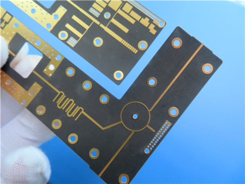
The DK2.2 F4B board is a compact two-layer rigid circuit of 36.4 mm x 88.76 mm (plus/minus 0.15 mm), one piece per build, finished to only 0.3 mm thickness. It is deliberately minimal: no legend or solder mask on either side, and no blind or buried vias, a typical choice for RF hardware where mask and legend would add uncontrolled dielectric variation. Both outer layers carry 1 oz (about 35 um) copper, the smallest hole is 0.4 mm, vias are plated to 20 um, and the finish is immersion gold. Minimum trace and space is 6/7 mil; artwork is Gerber RS-274-X to IPC-Class-2, and every board receives 100% electrical test before shipment.
Every fabrication parameter is condensed in the build specification below.
|
Parameter |
Value |
|
Layer count |
2-layer rigid |
|
Base material |
F4BTMS220 (PTFE + nano-ceramic, quartz glass cloth) |
|
Board dimensions |
36.4 mm x 88.76 mm (1 pc), +/- 0.15 mm |
|
Finished board thickness |
0.3 mm |
|
Finished copper weight (outer layers) |
1 oz (~35 um / 1.4 mil) |
|
Minimum trace / space |
6 / 7 mil |
|
Minimum drilled hole |
0.4 mm |
|
Blind / buried vias |
None |
|
Via plating thickness |
20 um |
|
Surface finish |
Immersion gold |
|
Silkscreen (top / bottom) |
No / No |
|
Solder mask (top / bottom) |
No / No |
|
Acceptance standard |
IPC Class 2 |
|
Artwork format |
Gerber RS-274-X |
|
Pre-shipment test |
100% electrical test |
|
Availability |
Worldwide |
With two copper layers, all RF behaviour is set by one thin core, as the stack-up shows.
|
Layer |
Description |
Thickness |
|
Copper Layer 1 |
Outer copper foil (signal / ground) |
35 um (1 oz) |
|
Dielectric core |
F4BTMS220 PTFE / ceramic core |
0.254 mm (10 mil) |
|
Copper Layer 2 |
Outer copper foil (ground / signal) |
35 um (1 oz) |
Etched and plated, the 0.3 mm finished thickness reflects this copper-core-copper stack.
The statistics show a small, component-light board whose complexity sits in its vias.
|
Item |
Count |
|
Components |
14 |
|
Total pads |
32 |
|
Through-hole pads |
19 |
|
Top-side SMT pads |
13 |
|
Bottom-side SMT pads |
0 |
|
Vias |
11 |
|
Nets |
2 |
PCB Conclusion
Read together, the tables describe a thin, flat 2-layer RF boardrather than a dense digital assembly. The 10mil F4BTMS220 core and 1 oz copper set the controlled-impedance lines; the 0.4 mm hole and 20 um via plating set the via reliability budget; and the absence of mask and legend keeps the dielectric stack pure. Immersion gold gives the planar, tarnish-resistant contact finish expected on microwave hardware, while 100% electrical test and IPC-Class-2 set a consistent quality baseline. This is the right form factor for a filter, feed network, antenna transition or small phased-array element.
Part B — The F4BTMS220 CCL: The Material Behind the Board
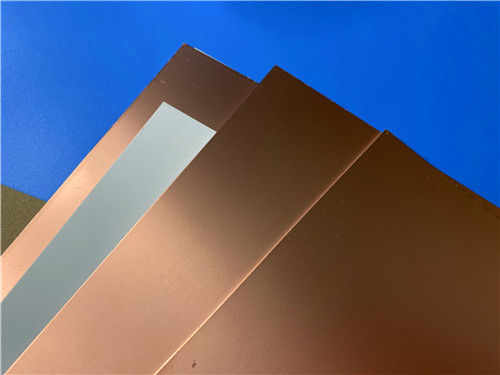
F4BTMS220 is a PTFE-based copper-clad laminate for aerospace and microwave use. It combines PTFE resin with a high loading of uniformly distributed nano-ceramics and only a little ultra-thin, ultra-fine quartz glass cloth. That is the key decision: woven fibreglass raises effective Dk and creates local variation as a wave crosses glass bundles and resin-rich regions. By minimising the glass fraction and using ceramic filler, F4BTMS220 substrate lowers dielectric loss, reduces X/Y/Z anisotropy, extends the usable frequency, raises electrical strength and thermal conduction, and tightens dimensional stability. It ships with RTF low-roughness copper foil, cutting conductor loss while keeping peel strength above 2.4 N/mm.
These properties give predictable RF performance. A tight Dk tolerance of +/-0.02 and low lot variation keep feed-network lengths and impedance from drifting between boards, which matters when phase error sets array sidelobe and pointing. Dissipation factor rises only from 0.0009 at 10 GHz to 0.0013 at 40 GHz, staying loss-efficient into millimetre-wave bands, while a Dk temperature coefficient of -130 ppm/degC over -55 to 150 degC keeps phase stable. Low CTE (40/50 ppm in X/Y), UL-94 V-0, 0.02% moisture absorption, vacuum-compatible outgassing and radiation resistance extend the board into space and radar.
The complete datasheet below lets every claim be checked against a measured value.
|
Property |
Condition |
Unit |
Value |
|
Dielectric constant, typical |
10 GHz |
- |
2.2 |
|
Dk tolerance |
- |
- |
+/- 0.02 |
|
Dielectric constant, design |
10 GHz |
- |
2.2 |
|
Dissipation factor |
10 GHz |
- |
0.0009 |
|
Dissipation factor |
20 GHz |
- |
0.0010 |
|
Dissipation factor |
40 GHz |
- |
0.0013 |
|
Dk temperature coefficient |
-55 to 150 degC |
ppm/degC |
-130 |
|
Peel strength (1 oz RTF) |
- |
N/mm |
>2.4 |
|
Volume resistivity |
Room temp |
Mohm.cm |
>= 1x10^8 |
|
Surface resistance |
Room temp |
Mohm |
>= 1x10^8 |
|
Dielectric strength (Z) |
5 kV, 500 V/s |
kV/mm |
>26 |
|
Breakdown voltage (X/Y) |
5 kV, 500 V/s |
kV |
>35 |
|
CTE X / Y |
-55 to 288 degC |
ppm/degC |
40 / 50 |
|
CTE Z |
-55 to 288 degC |
ppm/degC |
290 |
|
Thermal stress |
260 degC, 10 s x3 |
- |
No delamination |
|
Moisture absorption |
20+/-2 degC, 24 h |
% |
0.02 |
|
Density |
Room temp |
g/cm3 |
2.18 |
|
Long-term use temperature |
- |
degC |
-55 to +260 |
|
Thermal conductivity (Z) |
- |
W/(m.K) |
0.26 |
|
Flammability |
- |
UL-94 |
V-0 |
|
Composition |
- |
- |
PTFE + quartz glass cloth |
The F4BTMS laminate is build-flexible: foil in 0.5 oz (0.018 mm) or 1 oz (0.035 mm) with RTF standard, and optional 50 ohm embedded-resistor, copper-base or aluminium-base versions where shielding or heat spreading is needed. Standard sheets are 305x460, 460x610 and 610x920 mm; dielectric thicknesses run from 0.09 mm upward, the 10 mil core being one standard step. It processes on a standard PTFE flow, so the same material scales to multilayer backplanes and dense-hole, fine-line designs.
CCL Conclusion
F4BTMS220 is not a generic FR-4 substitute: its PTFE-ceramic chemistry, +/-0.02 Dk tolerance, 0.0009 loss and RTF copper target phase-critical RF. For this two-layer immersion-gold board, those properties fix impedance, loss and thermal reliability before layout. Designers in microwave, radar, feed-network and satellite work can treat the datasheet values as the performance floor, then tune the geometry around them with confidence.





If you have questions or suggestions,please leave us a message,we will reply you as soon as we can!
Categories
New Products

Wangling F4BTMS220 2-Layer DK2.2 PCB 10 mil Core with Immersion Gold

Wangling F4BTME350 10mil DK3.5 High Frequency Substrate PCB 2-Layer Immersion Gold

Wangling F4BTM300 Custom 2-layer PCB 20mil DK3.0 Substrate with Immersion Gold

Rogers 20mil RT/duroid 6202 2-layer ENIG High-Frequency Microwave PCB

Rogers 20mil AD250C PCB Pure Gold High-Frequency Antenna Circuit Board

8-Layer Hybrid RF PCB: RO4350B + TG170 FR-4 + RO4003C with RO4450F Bondply

4-Layer Rogers RO3010 Hybrid PCB Immersion Silver 2.8mm Finished Thickness

4-Layer 20mil Rogers RO3210 ISIG High-Frequency PCB with Controlled Depth Milling
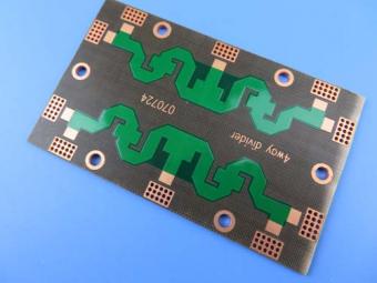
Polytetrafluoroethylene (Short for PTFE), commonly known as "plastic king ", is a polymer compound made of tetrafluoroethylene by polymerization. It has excellent chemical stability, corrosion resistance, sealing, high lubrication and non-viscosity, electrical insulation and good aging resistance.
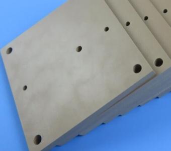
Rogers TMM4 thermoset microwave material is ceramic, hydrocarbon, thermoset polymer composite designed for high plated-through-hole reliability stripline and microstrip applications.
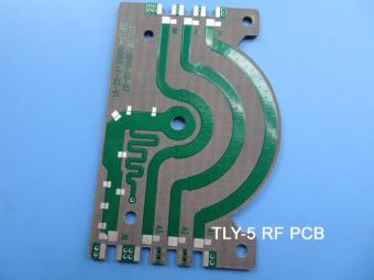
Taconic TLY laminates are a type of low loss laminates. They are manufactured with very light weight woven fiberglass and are more dimensionally stable than chopped fiber reinforced PTFE composites.
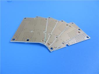
RO3203 laminates combine the surface smoothness of a non-woven PTFE laminate, for finer line etching tolerances, with the rigidity of a woven-glass PTFE laminate. These materials can be fabricated into printed circuit boards using
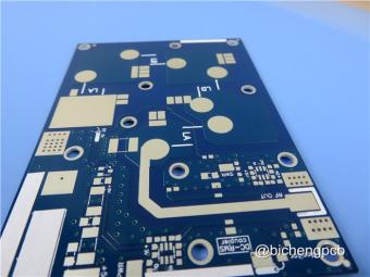
This type of immersion silver RF PCB is made on one of Taconic’s ORCER family material: RF-45.
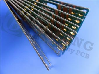
Rogers’ TMM10 thermoset microwave materials are ceramic, hydrocarbon, thermoset polymer composites designed for high plated-thru-hole reliability stripline and microstrip applications.
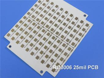
Rogers RO3006 was designed to offer exceptional electrical and mechanical stability at competitive prices.
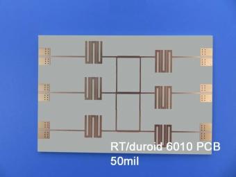
RT/duroid 6010LM microwave laminates feature ease of fabrication and stability in use. This property results in the possibility of mass production and reducing the cost of goods.
 6-11C Shidai Jingyuan, Fuyong, Baoan, Shenzhen, Guangdong, China 518103


For inquiries about our products or pricelist, please leave to us and we will be in touch within 24 hours.
© Copyright: 2026 Shenzhen Bicheng Electronics Technology Co., Ltd.. All Rights Reserved.

IPv6 network supported


